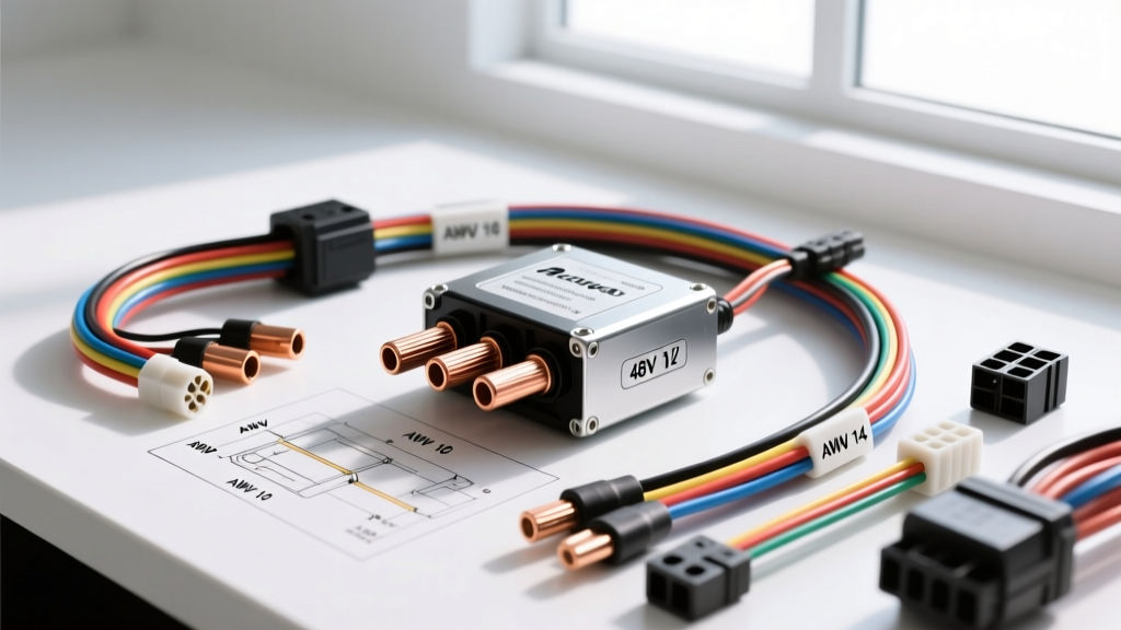
The Architecture of 48V Carts and the 12V Accessory Problem
Modern 48V electric golf carts, such as the Club Car Precedent, EZ-GO RXV, and Yamaha Drive, utilize either six 8V deep-cycle batteries or four 12V AGM/Lithium batteries wired in series. When owners install 12V accessories—like LED light kits, Bluetooth stereos, or USB chargers—a common but destructive mistake is tapping into just one or two batteries in the pack to get 12V. This creates a severe state-of-charge imbalance, leading to premature sulfation, stratification, and catastrophic pack failure. The only correct solution is utilizing a high-efficiency DC-DC buck converter. This guide provides a comprehensive product comparison, selection criteria, and a universal 48v to 12v golf cart voltage reducer wiring diagram to ensure your accessory bus is safe, efficient, and balanced.
Product Comparison: Selecting the Right Voltage Reducer
Not all DC-DC step-down converters are created equal. Linear regulators waste massive amounts of energy as heat, whereas modern synchronous buck converters operate at 90-96% efficiency. Below is a comparison of the most common 48V to 12V reducers used in light electric vehicles (LEVs).
| Brand / Model | Topology | Max Output | Cooling / IP Rating | Best Application |
|---|---|---|---|---|
| Club Car OEM (101972901) | Synchronous Buck | 10A (120W) | Finned Aluminum / IP54 | OEM replacements, basic LED lights |
| Lerds Heavy Duty 15A | Synchronous Buck | 15A (180W) | Potted Resin / IP67 | Light bars, small audio amps |
| Drok Waterproof 20A | Synchronous Buck | 20A (240W) | Sealed Alloy / IP68 | Winches, coolers, full stereo systems |
| Generic 30A Unbranded | Switching Buck | 30A (360W) | Fan-cooled / IP20 | Not recommended (fan failure risk) |
Selection Verdict: For 90% of golf cart builds, the Drok Waterproof 20A or Lerds 15A is the optimal choice. The fully potted, fanless IP67/IP68 designs eliminate the risk of dust ingress and cooling fan failure, which are the leading causes of reducer burnout in off-road and golf course environments.
Universal 48V to 12V Golf Cart Voltage Reducer Wiring Diagram
While OEM harnesses vary slightly between EZ-GO, Yamaha, and Club Car, the fundamental DC-DC wiring topology remains identical. Below is the exact pinout, wire color code, and routing specification for a universal 4-wire or 3-wire reducer setup.
Input Side: 48V Battery Pack Connection
The input side must connect to the entire 48V pack to draw current evenly across all cells. Never connect the input ground to a localized chassis ground; golf cart chassis grounds are notoriously unreliable and can cause voltage ripple.
- Input Positive (Red Wire): Connect to the Main Pack Positive terminal (the first positive post in the series chain). Use a 3/8-inch tinned copper ring terminal, crimped with a hex-crimp tool, and sealed with 3M Scotchcast dielectric resin.
- Input Negative (Black Wire): Connect to the Main Pack Negative terminal (the final negative post completing the 48V circuit).
- Inline Fusing: Install a MAXI or ANL fuse holder on the Red Input wire within 6 inches of the battery terminal. For a 20A output reducer, the 48V input draw will be roughly 6.5A (accounting for 92% efficiency). A 15A inline fuse is required on the 48V side.
Output Side: 12V Accessory Bus Connection
The output side feeds your 12V fuse block or direct accessories. Most high-quality reducers feature a 3-wire output (Red, Yellow, Black) to support both constant and switched 12V sources.
- Output Constant 12V (Red Wire): Provides unswitched 12V. Connect to a marine-grade Blue Sea Systems fuse block for accessories that require constant memory (e.g., radio presets, GPS trackers).
- Output Switched 12V (Yellow Wire): Many reducers tie the yellow wire to an internal relay triggered by a 12V signal. If your reducer is a standard 2-wire output, you must install an external 12V automotive relay (Bosch style, 30A) triggered by the cart's key switch or tow/run switch to prevent parasitic drain when the cart is parked.
- Output Ground (Black Wire): Connect directly to the 12V fuse block negative bus bar. From the bus bar, run a dedicated 8 AWG ground wire back to the Main Pack Negative terminal to ensure a clean, low-resistance return path.
AWG Sizing and Fusing Specifications
Adhering to SAE J1128 standards for low-tension primary cable is critical to prevent voltage drop and insulation melting. Golf carts operate in high-ambient-temperature environments, requiring copper wiring (never Copper-Clad Aluminum, CCA) with cross-linked polyethylene (XLPE) or PVC insulation rated for 105°C.
| Reducer Output Rating | 48V Input AWG | 48V Input Fuse | 12V Output AWG | 12V Main Fuse |
|---|---|---|---|---|
| 10A (120W) | 14 AWG | 10A | 12 AWG | 15A |
| 15A (180W) | 12 AWG | 15A | 10 AWG | 20A |
| 20A (240W) | 10 AWG | 15A | 8 AWG | 25A |
| 30A (360W) | 8 AWG | 20A | 6 AWG | 35A |
Real-World Troubleshooting & Failure Modes
Even with a perfect wiring diagram, environmental factors and poor termination can cause system failures. Use a digital multimeter (DMM) to diagnose these common LEV electrical issues.
Symptom: Reducer Shuts Down Under Load (Thermal Rollback)
Cause: Most premium reducers feature internal thermal protection that throttles or cuts output if the casing exceeds 85°C. This is usually caused by mounting the reducer in an enclosed battery compartment without airflow, or using undersized input wiring that forces the converter to work harder to compensate for voltage drop. Fix: Relocate the reducer to the underside of the seat pan or the front cowl where ambient air flows. Ensure all ring terminals are torqued to battery manufacturer specifications (typically 90-120 in-lbs for 3/8" hardware) to minimize contact resistance.
Symptom: Premature Battery Sulfation and Uneven Run Times
Cause: The reducer was wired to a single 8V or 12V battery instead of the main pack terminals. According to the Battery Council International (BCI), drawing unequal current from a series string causes the tapped battery to chronically undercharge, leading to hard lead sulfate crystal formation on the negative plates. Fix: Reroute the 10 AWG input wires to the absolute first positive and last negative posts of the 48V series chain. Perform an equalization charge (if using flooded lead-acid) or a top-balance cycle (if using LiFePO4) to recover the damaged cell.
Symptom: Audio Alternator Whine or LED Flickering
Cause: High-frequency switching noise (voltage ripple) from the DC-DC buck converter is bleeding into the 12V accessory bus. This is common with cheap, unshielded generic reducers. Fix: Verify the reducer's output ripple is under 100mV peak-to-peak using an oscilloscope or a DMM set to AC millivolts. If ripple is high, install a 10,000µF electrolytic filtering capacitor across the 12V positive and negative bus bars near the stereo amplifier or LED driver to smooth the DC waveform.
Authoritative References & Further Reading
- SAE International: J1128 Low Tension Primary Cable Standards - Guidelines for AWG sizing, insulation temperature ratings, and voltage drop limits in 12V-48V automotive and LEV applications.
- Battery Council International (BCI): Battery Sulphation and Imbalance - Technical data on the electrochemical degradation of deep-cycle batteries when subjected to asymmetric series-string loading.
- Club Car Official Owner & Service Manuals - OEM wiring schematics, torque specifications for battery interconnects, and approved accessory routing channels for DS and Precedent platforms.