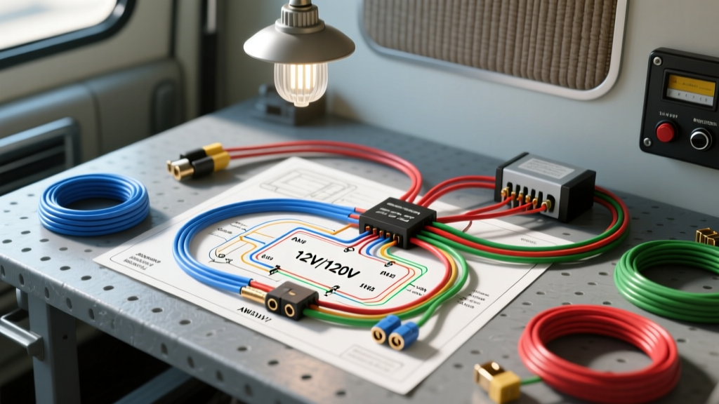
Adapting Residential Lighting to Mobile 12V/120V Systems
In the world of high-end custom motorhomes, luxury Sprinter van conversions, and limousine upfits, interior designers frequently specify residential-grade crystal lighting. However, adapting a standard residential wiring diagram for chandelier fixtures into a mobile automotive environment introduces severe electrical conflicts. A home relies on a stable 120V AC, 60Hz pure sine wave grid. A vehicle relies on a 12V DC alternator/battery bank, converted to 120V AC via an inverter. When upfitters blindly follow residential wiring schematics without accounting for automotive DC-to-AC inversion, the result is flickering LEDs, tripped GFCI outlets, destroyed LED drivers, and inverter overload faults.
This guide provides a step-by-step troubleshooting flow and technical wiring schematics for integrating and diagnosing 120V AC chandelier circuits powered by a vehicle's 12V DC inverter system, adhering to RV Industry Association (RVIA) standards and SAE J1128 automotive cable specifications.
The Core Conflict: Waveform Distortion and LED Drivers
Most modern chandeliers utilize integrated LED modules with internal switching power supplies (drivers). These drivers are highly sensitive to Total Harmonic Distortion (THD). If your vehicle is equipped with a Modified Sine Wave (MSW) inverter, the stepped voltage waveform will cause the chandelier's LED drivers to overheat, buzz audibly, and flicker at 120Hz.
Diagnostic Rule #1: Always verify the inverter topology. For any residential wiring diagram for chandelier installations to function correctly in an RV or custom truck, the power source must be a Pure Sine Wave (PSW) inverter with a THD of less than 3%. Reference Victron Energy Inverter Manuals for PSW output specifications.
Step-by-Step Troubleshooting Flow
Use the following decision tree to diagnose failures in your custom vehicle chandelier circuit. You will need a digital multimeter (DMM), an oscilloscope (for THD verification), and a clamp meter.
Symptom 1: Chandelier Flickers or Buzzes When Engine is Running
- Step 1: Measure DC voltage at the inverter's positive and negative busbars with the engine idling (alternator charging). Expect 13.8V to 14.4V DC.
- Step 2: If voltage fluctuates rapidly or drops below 13.2V under load, check the DC feed wire gauge. Voltage drop at the inverter input causes the AC output waveform to clip, creating harmonics that manifest as flickering in the chandelier.
- Step 3: Inspect the chassis ground. If the inverter negative terminal is grounded to a painted chassis rail rather than a dedicated copper busbar tied directly to the battery bank, high-frequency alternator ripple will bleed into the AC output.
- Fix: Upgrade the DC feed to 2/0 AWG welding cable and install a dedicated 500A DC shunt and busbar system.
Symptom 2: Inverter Throws GFCI or Over-Current Fault Upon Switching On
- Step 1: Residential chandeliers often feature large toroidal transformers (for halogen conversions) or high-capacitance LED drivers. When switched on, these draw a massive inrush current (sometimes 10x the running wattage for 20 milliseconds).
- Step 2: Check the inverter's AC output breaker. If a standard residential 15A thermal breaker is used, it may misinterpret the inrush current as a short circuit.
- Step 3: Measure the AC Safety Ground (Green wire). In a vehicle, the AC safety ground must be bonded to the vehicle chassis only at the inverter's internal transfer switch or main AC panel. If the chandelier's metal canopy is accidentally grounded to the vehicle's 12V DC chassis ground via a mounting screw, it creates a ground loop, tripping the inverter's internal GFCI.
- Fix: Isolate the chandelier mounting canopy using nylon washers and ensure the AC ground wire (12 AWG Green) is routed exclusively back to the inverter's AC ground bus.
Symptom 3: Dimmer Switch Causes Strobe Effect or Complete Shutoff
- Step 1: Identify the dimmer type. Standard residential Triac (leading-edge) dimmers chop the AC sine wave. When paired with an inverter and low-wattage LED chandeliers, the chopped wave prevents the inverter's feedback loop from regulating voltage, causing a strobe effect.
- Step 2: Verify if the dimmer is located on the 120V AC side or the 12V DC side.
- Fix: Remove the 120V AC Triac dimmer. Instead, use a 12V DC PWM (Pulse Width Modulation) dimmer on the low-voltage side of a dedicated lighting relay, or install an ELV (Electronic Low Voltage) trailing-edge dimmer rated specifically for inverter power.
Automotive Wire Sizing & Routing Specifications
When executing the wiring diagram for chandelier power feeds in a mobile application, voltage drop is the primary enemy. The following table outlines the mandatory SAE J1128 compliant wire sizing for a standard 2000W Inverter setup powering a luxury lighting package.
| Circuit Segment | Wire Gauge (AWG) | SAE Color Code | Max Length (One Way) | Protection / Fuse Rating |
|---|---|---|---|---|
| Battery Bank to Inverter DC Feed | 2/0 AWG | Red (Pos) / Black (Neg) | 5 ft (1.5m) | 250A ANL Fuse |
| Inverter AC Out to Main Junction Box | 12 AWG (Stranded) | Black / White / Green | 15 ft (4.5m) | 20A Hydraulic-Magnetic Breaker |
| Junction Box to Chandelier Canopy | 14 AWG (Stranded) | Black / White / Green | 10 ft (3m) | Protected by Main Breaker |
| 12V Dash Switch to Isolation Relay | 18 AWG | Blue | 12 ft (3.6m) | 5A ATO Blade Fuse |
Relay Isolation Schematic: Protecting the Inverter Remote
Never wire a 12V DC dashboard toggle switch directly to a 120V AC inverter's remote enable terminal. The remote terminal is highly sensitive to voltage spikes and alternator noise. Instead, use a standard Bosch-style 5-pin automotive relay (ISO 7588) to isolate the 12V DC trigger circuit from the inverter's logic board.
Bosch 5-Pin Relay Pinout Configuration
- Pin 30 (Common): Connect to a fused 12V DC constant power source (Red wire, 14 AWG).
- Pin 87 (Normally Open): Connect to the Inverter's 'Remote Enable' or 'Ignition Sense' terminal.
- Pin 86 (Coil Ground): Connect to a clean, dedicated 12V DC chassis ground ring terminal.
- Pin 85 (Coil Trigger): Connect to the 12V DC output of your dashboard toggle switch or smart-home RV controller (Blue wire).
- Pin 87a (Normally Closed): Not used; tape off or heat-shrink.
Pro-Tip: Install a 1N4001 flyback diode across Pins 85 and 86 (stripe facing Pin 85) to suppress the inductive kickback generated when the relay coil de-energizes. This prevents voltage spikes from resetting the vehicle's CAN bus or damaging the inverter's remote logic circuit.
Grounding Protocols: Chassis vs. AC Safety Ground
The most critical failure point when adapting a residential wiring diagram for chandelier fixtures to an RV is the misunderstanding of grounding. In a house, the Neutral (White) and Ground (Green/Bare) are bonded at the main service panel. In a vehicle with an inverter/charger, this bonding must only occur inside the inverter's automatic transfer switch when operating on shore power, or via a dedicated ground relay when inverting.
If you manually bond the chandelier's AC neutral to the vehicle's DC chassis ground at the fixture canopy, you will bypass the inverter's internal GFCI sensors. The moment the chandelier draws current, the inverter will detect the neutral-to-ground fault and instantly sever AC power to prevent chassis electrocution. Always run a dedicated 12 AWG Green AC safety ground wire all the way from the chandelier canopy back to the inverter's AC ground busbar, keeping it completely isolated from the 12V DC vehicle chassis.
Summary of Best Practices
Successfully integrating high-end residential lighting into automotive platforms requires respecting both domains. Use Pure Sine Wave inversion, calculate DC voltage drop rigorously using SAE J1128 standards, isolate your remote triggers via automotive relays, and maintain strict separation between 12V DC chassis grounds and 120V AC safety grounds. By following this troubleshooting flow, custom upfitters can ensure that luxury lighting performs flawlessly on the road.