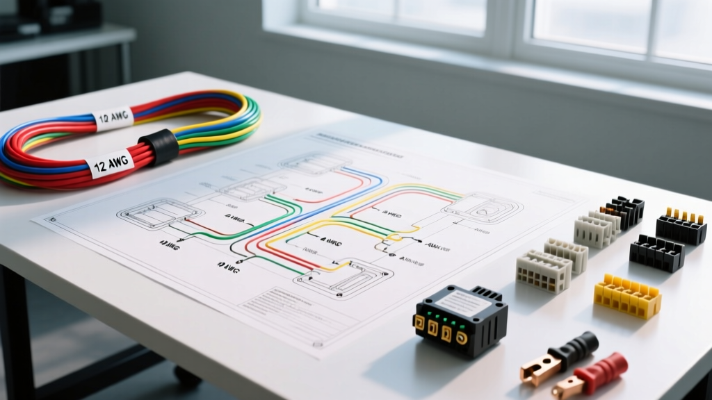
Why Your Modification Needs a Custom Electrical Wiring Diagram Drawing
When upgrading a 4x4 platform with high-draw accessories like LED light bars, winches, onboard air compressors, and dual-battery isolators, relying on mental notes or scrap paper is a recipe for electrical fires and parasitic draws. A precise electrical wiring diagram drawing is the blueprint that bridges the gap between a safe, reliable build and a stranded vehicle with melted harnesses. Professional automotive electricians do not guess; they calculate, draft, and execute.
Creating a comprehensive schematic before cutting a single zip tie ensures you account for voltage drop, inrush currents, and proper grounding topology. This guide details how to draft, interpret, and execute a custom wiring diagram for heavy-duty off-road modifications, adhering to SAE (Society of Automotive Engineers) standards.
Phase 1: Load Calculation and AWG Sizing Strategy
Before drawing a single line on your schematic, you must calculate the total amperage draw of your planned accessories. The most common failure mode in aftermarket 4x4 wiring is undersized cabling, which leads to severe voltage drop. This not only dims your lights but can cause sensitive ECU modules to reset due to low-voltage conditions.
For engine bay and chassis routing, always specify SAE J1128 TXL (Thin-wall cross-linked) or GXL wire on your diagram. TXL is rated for 125°C, making it ideal for proximity to exhaust manifolds and engine blocks. Standard PVC wire (like primary wire) will melt and short out under hood temperatures.
Table 1: SAE J1128 TXL Wire Sizing & Amperage Limits
| AWG Size | Max Amperage (Engine Bay) | Max Amperage (Cabin/Chassis) | Typical Application |
|---|---|---|---|
| 10 AWG | 30A | 40A | LED Light Bars, Horns, Fuel Pumps |
| 8 AWG | 40A | 55A | CB Radios, Small Winch Solenoids |
| 6 AWG | 55A | 75A | Onboard Air Compressors, Inverters |
| 4 AWG | 70A | 100A | Dual Battery Link Cables, Audio Amps |
| 2 AWG | 100A | 130A | Main Battery to Starter, Winch Power |
| 1/0 AWG | 150A+ | 200A+ | Heavy Duty Winch, Main Chassis Ground |
Note: Always apply a 20% safety margin to your calculated amperage draw when selecting wire gauge and fuse sizes on your drawing.
Phase 2: Standardizing Symbols and Relay Pinouts
A professional electrical wiring diagram drawing uses universally recognized symbols. When mapping out high-draw circuits, you must isolate the switch from the load using an automotive relay. This allows a low-amperage switch (e.g., a 5A dash toggle) to control a 40A light bar safely.
The standard ISO Mini Relay is the backbone of 4x4 modifications. Your schematic must clearly label the four critical pins to prevent miswiring, which can result in the switch carrying the full load or the relay coil burning out.
Table 2: Standard ISO Mini Relay Pinout Mapping
| Pin Number | Function | Wire Gauge | Drafting Symbol Note |
|---|---|---|---|
| 86 | Relay Coil (+) | 18-16 AWG | Connects to ignition-switched or dash switch power. |
| 85 | Relay Coil (-) | 18-16 AWG | Connects to a dedicated chassis ground. |
| 30 | Common (Power In) | 12-10 AWG | Direct from battery via main fuse block. |
| 87 | Normally Open (Out) | 12-10 AWG | Routes to the accessory (e.g., light bar positive). |
According to the Littelfuse Automotive Relay Application Guide, utilizing a diode or resistor across pins 85 and 86 on your diagram is highly recommended when driving relays via solid-state switches or ECUs to suppress inductive voltage spikes that can fry onboard computers.
Phase 3: SAE Color Coding and Circuit Topology
Color-coding your wiring diagram drawing is not just for aesthetics; it is a critical troubleshooting tool for the future. While custom harness builders often use their own palettes, adhering to SAE J1128 color conventions ensures that any qualified technician can read your schematic years down the road.
- Red: Unfused battery power or main power feeds.
- Black: Dedicated chassis or battery grounds.
- Yellow: Accessory circuits (switched via relays).
- Blue: High-beam or high-draw auxiliary lighting triggers.
- Green: Sensor returns or low-voltage signal wires.
- White: Ground returns for specific lighting circuits (often used in trailer harnesses).
When drawing your topology, implement a centralized power distribution block (such as a Blue Sea Systems ST busbar) rather than stacking multiple ring terminals on the positive battery post. Stacking terminals increases contact resistance and creates a single point of catastrophic failure. Your diagram should show main power feeding the busbar via a heavy-duty ANL or Class-T fuse, with individual circuits branching off with their own ATC/ATO blade fuses.
Phase 4: Grounding Strategy and Torque Specifications
The most overlooked aspect of an electrical wiring diagram drawing is the ground return path. A 12V circuit is only as good as its ground. Drawing a generic 'chassis ground' symbol is insufficient for high-amperage off-road builds. You must specify exact grounding nodes.
- Identify Bare Metal: Specify on the drawing that paint, powder coat, and undercoating must be removed using a flap disc or sandpaper down to bare steel.
- Anti-Oxidant Paste: Note the application of dielectric grease or copper anti-seize on the mating surface to prevent galvanic corrosion, especially in wet, muddy environments.
- Hardware and Torque: Use Grade 8 or stainless steel flange nuts. For an M8 ground stud, torque to 15-20 Nm (11-15 lb-ft). For an M6 stud, torque to 8-10 Nm (6-7 lb-ft). Under-torquing leads to arcing and heat; over-torquing strips the weld nut on the chassis.
For dual-battery setups, always draw the negative return cable from the auxiliary battery to the engine block or alternator bracket, not just the chassis frame. The engine sits on rubber isolator mounts, meaning the chassis ground is inadequate for the 150+ amps required during engine cranking.
Executing the Build: From Paper to Loom
Once your electrical wiring diagram drawing is finalized, the physical execution must match the schematic's rigor. Avoid soldering under-hood connections. Solder wicks moisture, becomes brittle under engine vibration, and creates a hard point that leads to wire fatigue and breakage. Instead, specify ratcheting crimp tools and adhesive-lined (dual-wall) heat shrink terminals on your build sheet.
When routing the harness, use split-loom tubing or Techflex braided sleeving, securing it every 8 to 12 inches with UV-resistant nylon zip ties or P-clips bolted to existing factory harness points. Keep high-amperage power cables separated from low-voltage CAN-bus or sensor wiring by at least 4 inches to prevent Electromagnetic Interference (EMI), which can cause erratic shifting or check engine lights.
Common Drafting Mistakes to Avoid
Even experienced fabricators make errors when drafting custom schematics. Review your drawing for these common pitfalls:
- Ignoring Inrush Current: Incandescent lights and electric motors (like winches or air compressors) draw 2 to 3 times their running amperage for the first few milliseconds. Size your fuses using time-delay (slow-blow) characteristics for inductive loads, as noted in SAE J1128 standards.
- Switching the Ground Side: Always draw your switches and fuses on the positive (+) side of the circuit. Switching the ground side leaves the accessory energized at all times, creating a severe short-to-ground fire hazard if the wire chafes against the chassis.
- Omitting Fuse Locations: Your drawing must explicitly state that the main circuit fuse is located within 18 inches of the power source. An unfused wire running 10 feet from the battery to the firewall is a dead short waiting to happen.
Conclusion
A meticulously crafted electrical wiring diagram drawing is the hallmark of a professional 4x4 build. By calculating voltage drop, utilizing SAE-compliant TXL wire, mapping ISO relay pinouts, and engineering robust ground nodes, you ensure your vehicle's electrical system can handle the brutal demands of the trail. Take the time to draft, review, and refine your schematic before picking up your wire strippers—your vehicle's reliability depends on it.
For further reading on heavy-duty circuit protection and harness routing, refer to the Painless Performance Wiring Manuals and SAE International automotive standards.