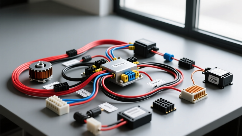
The 110cc Engine Swap: Moving Beyond the Magneto
When executing a custom pit bike build, go-kart fabrication, or an ATV engine swap, the generic 110cc horizontal engine is a staple of the motorsport community. However, most factory 110cc engines ship with a rudimentary AC magneto stator designed solely to fire the spark plug. If your upgrade and modification project involves adding LED lighting, a digital dashboard, a horn, or an electric start, the factory AC system will not suffice. You must convert the platform to a 12V DC system.
These comprehensive 110cc wiring diagram instructions will guide you through the complete rewiring process. We will cover the integration of a DC stator, a 4-pin rectifier/regulator, a 6-pin DC CDI, and the necessary relay logic for high-draw accessories. By following these schematic guidelines, you will build a robust, weather-resistant electrical harness capable of handling the rigors of off-road racing and custom street-legal conversions.
Component Breakdown for 12V DC Conversions
Before cutting and crimping, you must source the correct upgrade components. The standard 110cc AC stator features a source coil (Black/Red) that generates high voltage directly for an AC CDI. To upgrade, you must replace the stator with a 12V DC lighting coil variant, which eliminates the source coil and replaces it with additional windings to output raw AC voltage to a rectifier.
The 5-Wire DC Stator Output
A standard upgraded 110cc stator typically outputs five wires. Understanding these is critical before consulting any 110cc wiring diagram instructions:
- Yellow Wire: Main AC lighting output (approx. 14V-16V AC at high RPM).
- White Wire: Secondary AC output (often used for a secondary lighting circuit or left capped if using a full-wave rectifier).
- Pink Wire: Pulse pickup coil signal (triggers the CDI).
- Green/White Wire: Pulse pickup ground reference.
- Green Wire: Main stator ground.
The 4-Pin Rectifier/Regulator
To convert the stator's raw AC voltage into stable 12V DC for your battery and accessories, a 4-pin shunt-style rectifier/regulator is required. According to testing protocols outlined by Electrosport Industries, a proper shunt regulator must be grounded effectively to dissipate excess voltage as heat. The pins are typically: Yellow (AC In), White (AC In), Red (DC 12V+ Out), and Green (Ground).
Step-by-Step 110cc Wiring Instructions
Follow this sequence to ensure proper current flow and prevent back-feeds that can destroy sensitive DC CDIs.
Step 1: Stator to Rectifier Routing
Route the stator wires through the engine case grommet. Use 16 AWG primary wire for the extensions to minimize voltage drop over the length of the chassis harness. Connect the Stator Yellow to the Rectifier Yellow. Connect the Stator White to the Rectifier White. Connect the Rectifier Red to your main battery positive terminal via a 10-amp inline fuse. Connect the Rectifier Green and Stator Green to your chassis star-ground point.
Step 2: 6-Pin DC CDI Integration
Upgrading to a DC CDI requires a stable 12V source. Unlike AC CDIs, a DC CDI draws its spark energy from the battery, not the stator source coil. This results in a stronger, more consistent spark at low RPMs. Wire the 6-pin connector as follows:
- Pin 1 (Black): Connect to the 'ON' terminal of your ignition key switch (12V+).
- Pin 2 (Green): Connect to chassis ground.
- Pin 3 (Pink/Blue): Connect to the Stator Pink wire (Pulse Pickup).
- Pin 4 (Black/White): Connect to the engine kill switch. The kill switch works by grounding this pin to halt the spark.
- Pin 5 (Black/Yellow): Connect to the primary positive terminal of the ignition coil.
- Pin 6 (Empty): Not used on standard 110cc applications.
Step 3: Ignition Coil and Spark Plug Routing
The ignition coil acts as a step-up transformer. Connect the primary positive terminal to the CDI Pin 5 (Black/Yellow). Connect the primary negative terminal to the chassis ground using 14 AWG wire to ensure a solid ground path for the high-voltage discharge. The secondary high-tension wire should route directly to an NGK CR6HSA spark plug cap equipped with an internal 5k-ohm resistor to prevent RFI interference with digital gauges.
110cc Stator and CDI Wire Color Reference Chart
| Component | Wire Color | Function | AWG Spec | Destination |
|---|---|---|---|---|
| Stator | Yellow | AC Lighting Output | 16 AWG | Rectifier Yellow |
| Stator | Pink | Pulse Pickup Signal | 18 AWG | CDI Pin 3 |
| Stator | Green | Main Ground | 14 AWG | Chassis Star Ground |
| Rectifier | Red | 12V DC Output | 12 AWG | Battery Positive (via 10A Fuse) |
| CDI | Black | 12V DC Ignition Feed | 16 AWG | Key Switch 'ON' Terminal |
| CDI | Black/White | Kill Switch Ground | 18 AWG | Handlebar Kill Switch |
| CDI | Black/Yellow | Ignition Trigger | 16 AWG | Ignition Coil Primary (+) |
Integrating Lighting and High-Draw Accessories
A common mistake in 110cc modification projects is routing high-draw LED headlights or auxiliary lights directly through the handlebar switch. This causes voltage drop, switch melting, and dim lighting. To adhere to SAE J1128 standards for low-tension primary cable usage and circuit protection, you must utilize automotive relays.
The 30/40 Amp Relay Logic
For an upgraded LED headlight pod drawing 4 amps, wire a standard Bosch-style 4-pin relay. Run 12 AWG wire from the battery positive to a 15-amp fuse, then to Relay Pin 30. Run 14 AWG wire from Relay Pin 87 to the headlight positive. Ground the headlight negative and Relay Pin 85 to the chassis. Finally, use 18 AWG wire from your handlebar light switch to trigger Relay Pin 86. This ensures the heavy current load bypasses the delicate handlebar switches entirely.
Professional Crimping and Connector Selection
The environment of a 110cc pit bike or ATV is hostile to electrical connections. Vibration, water, and mud will destroy standard butt splices and electrical tape. For the main harness, utilize Delphi Weather-Pack connectors with silicone seals and crimped terminals. For smaller sensor wires and the CDI plug, JST SM connectors with locking barbs are the industry standard. Always use a ratcheting crimp tool (such as the IWISS SN-28B or SN-48B) to ensure the terminal wire grip and insulation grip are properly deformed around the 16-18 AWG wire. Follow up with adhesive-lined dual-wall heat shrink over all exposed splices to prevent moisture ingress and galvanic corrosion.
Troubleshooting Common 110cc Electrical Gremlins
Even with perfect 110cc wiring diagram instructions, aftermarket components can introduce faults. Use this diagnostic matrix to resolve common issues:
- Symptom: Engine cranks but has no spark.
Cause: DC CDI is not receiving 12V, or the kill switch circuit is permanently grounded.
Fix: Use a multimeter to verify 12.6V at CDI Pin 1 with the key ON. Disconnect the Black/White kill switch wire from the CDI; if spark returns, the handlebar switch or wiring is shorted to ground. - Symptom: Battery overcharges and boils (reads 15V+ at high RPM).
Cause: Rectifier/Regulator ground failure.
Fix: A shunt regulator requires a perfect ground to bleed off excess AC voltage. Clean the rectifier mounting bolt and chassis contact point down to bare metal. Apply dielectric grease after securing. - Symptom: Headlights flicker in time with engine RPM.
Cause: Undersized battery or missing battery in a DC system.
Fix: A 12V DC lighting system requires a battery to act as a capacitor and smooth out the rectifier's pulsing DC output. Install a minimum 12V 4Ah sealed AGM or Lithium Iron Phosphate (LiFePO4) battery.
Final Verification and Testing
Before starting the engine, perform a continuity check on all ground circuits. Set your digital multimeter to the ohms setting and measure resistance between the engine block, the rectifier casing, and the battery negative terminal. The reading should be less than 0.5 ohms. Once verified, connect the battery, turn the key to the 'ON' position, and verify the neutral light and dash illumination. With the kill switch in the 'RUN' position, engage the starter or kickstart the engine. A properly executed 110cc 12V conversion will yield a bright, consistent spark, stable idle, and robust lighting performance that outshines factory setups.