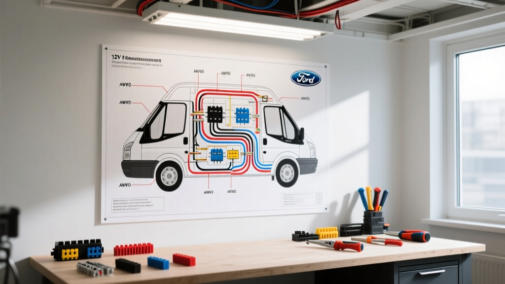
The Danger of Residential Logic in 12V DC Upfitting
When commercial upfitters and DIY van-lifers begin converting cargo vans like the Ford Transit, Ram ProMaster, or Mercedes Sprinter, one of the most common searches they perform is for a wiring diagram for ceiling light installations. The critical danger lies in the search results: most top-ranking diagrams are designed for 120V AC residential home wiring. Applying residential alternating current (AC) logic to a 12V or 24V direct current (DC) automotive platform is not just inefficient—it is a primary cause of vehicle electrical fires, melted harnesses, and destroyed alternators.
In a home, a 120V circuit drawing 1 amp requires minimal wire thickness. In a 12V DC vehicle, powering that same 120-watt load requires 10 amps of continuous current, generating significantly more heat and suffering from severe voltage drop over distance. This guide outlines the correct automotive-grade wiring diagram for ceiling light arrays, highlights catastrophic upfitter mistakes, and provides actionable safety warnings based on SAE and NFPA standards.
The Correct 12V Wiring Diagram for Ceiling Light Arrays
A proper automotive ceiling light array does not wire LEDs in a simple daisy-chain off a single switch. Modern commercial vans utilize upfitter switch banks and relay modules to protect the vehicle’s Body Control Module (BCM) and CAN-bus systems. Below is the standard routing for a 12V DC LED ceiling array drawing up to 10 amps (approximately 120 watts of LED lighting).
Step-by-Step 12V Routing & Pinout
- Power Source: Connect 12 AWG primary power wire directly to the auxiliary battery positive terminal or the OEM upfitter power distribution point.
- Primary Protection: Install a 15A MIDI or MAXI fuse within 18 inches of the power source. Never skip this step.
- Relay Control: Route 14 AWG wire to the load side of a heavy-duty solid-state relay or a standard Bosch-style 5-pin relay.
- Switch Signal: Use 18 AWG wire from the OEM dash upfitter switch (or auxiliary toggle) to trigger the relay coil (Pin 86). Pin 85 goes to a clean chassis ground.
- Load Distribution: From the relay output (Pin 87), run 14 AWG wire to a centralized marine-grade terminal block or fuse distribution bus located in the ceiling cavity.
- Branch Pigtails: From the distribution bus, run 18 AWG pigtails to individual LED ceiling pods.
Bosch-Style Relay Pinout for Upfitter Switches
| Pin Number | Function | Wire Color (SAE) | Connection Point |
|---|---|---|---|
| 30 | Common (Input) | Red (12 AWG) | Fused 12V+ Battery Source |
| 87 | Normally Open (Output) | Red (14 AWG) | Ceiling Light Distribution Bus |
| 85 | Coil Ground | Black (18 AWG) | Dedicated Ground Busbar |
| 86 | Coil Trigger (Input) | White (18 AWG) | Dash Upfitter Switch Output |
| 87a | Normally Closed | Not Used | Capped / Heat Shrinked |
4 Fatal Upfitter Mistakes & Safety Warnings
When adapting a residential wiring diagram for ceiling light setups into a vehicle, upfitters frequently make four catastrophic errors. Understanding these is vital for passing commercial DOT inspections and preventing thermal events.
Mistake 1: The RVIA vs. SAE J1128 Color Code Collision
One of the most dangerous traps in vehicle wiring is the collision between RV Industry Association (RVIA) standards and SAE J1128 automotive standards.
- SAE J1128 (Automotive): Red is 12V+ Positive. Black is Ground/Negative.
- RVIA (Recreational Vehicles): Black is 12V+ Positive. White is Ground/Negative.
- Residential AC (Home): Black is Hot. White is Neutral. Bare is Ground.
Mistake 2: Wire Nuts and Residential Connectors
Using twist-on wire nuts or push-in residential connectors (like Wago 221 series) in a vehicle ceiling cavity is a severe safety violation. Vehicles experience constant high-frequency vibration, thermal expansion/contraction, and torsional flex. Wire nuts will back off over time, leading to high-resistance arcing. Arcing in a confined, insulated ceiling cavity surrounded by wood framing and polyurethane spray foam is a leading cause of camper van fires.
The Fix: Use only marine-grade adhesive-lined heat shrink crimps, ultrasonic welds, or sealed automotive connectors like the Deutsch DT series or TE Connectivity AMP Superseal 1.5. These feature positive locking mechanisms and silicone seals that prevent moisture ingress and vibration-induced disconnects.
Mistake 3: Fusing the Switch Side Instead of the Source
A common error derived from household wiring diagrams is placing the fuse near the switch or the light fixture. In a 12V DC automotive system, the fuse must be placed within 18 inches of the power source (battery or distribution block). If a rodent chews through the 14 AWG wire routing through the B-pillar, or if the wire rubs against a sharp sheet metal edge behind the headliner, an unfused wire will draw hundreds of amps directly from the battery, welding the wire to the chassis and igniting the interior trim before the switch ever melts.
Mistake 4: Chassis Grounding to Thin-Gauge Sheet Metal
Modern unibody vans like the Ford Transit use high-strength, thin-gauge boron steel and extensive factory e-coat (paint) for rust prevention. Screwing a ring terminal directly into the roof rib or B-pillar provides a terrible ground. The paint acts as a dielectric insulator, and the thin metal cannot handle high-amperage return paths, leading to voltage drop, flickering LEDs, and localized heat buildup.
The Fix: Run all ceiling light grounds to a centralized, heavy-duty copper ground busbar. From that busbar, run a single 10 AWG or 8 AWG ground wire down the B-pillar to a dedicated, factory-designated chassis ground stud, ensuring you sand away the e-coat to bare metal and apply dielectric grease to prevent corrosion.
Voltage Drop & AWG Sizing Chart
Because 12V systems operate at a fraction of residential voltage, amperage must increase to deliver the same wattage, making voltage drop the enemy of LED ceiling arrays. If voltage drops below 11.5V at the LED driver, lights will flicker, change color temperature, or fail to turn on. Use the following chart for sizing your main trunk wire from the relay to the ceiling distribution block.
| Total LED Array Draw | One-Way Run Length | Required AWG Size (Copper) | Expected Voltage Drop |
|---|---|---|---|
| 5 Amps (60W) | 10 Feet | 16 AWG | 0.20V (1.6%) |
| 10 Amps (120W) | 10 Feet | 12 AWG | 0.16V (1.3%) |
| 10 Amps (120W) | 20 Feet | 10 AWG | 0.25V (2.0%) |
| 15 Amps (180W) | 25 Feet | 8 AWG | 0.24V (2.0%) |
Note: Always calculate voltage drop based on the total round-trip circuit length (Power + Ground) when using online calculators, though the chart above assumes standard chassis-return or parallel ground runs.
Troubleshooting CAN-Bus Interference & PWM Dimmers
A highly specific issue in modern vehicles (2015+ Transit, Sprinter, and ProMaster) involves LED ceiling light drivers causing CAN-bus interference. Cheap LED drivers utilize Pulse Width Modulation (PWM) at low frequencies. This electrical noise bleeds back into the vehicle’s 12V network, causing the alternator to whine through the stereo, or worse, triggering phantom Check Engine Lights (CEL) and BCM faults.
If you experience flickering ceiling lights when the engine is running, or if the dash throws a "Battery Not Charging" warning after installing your ceiling array, you are likely dealing with EMI (Electromagnetic Interference).
- Solution 1: Install a 12V DC EMI filter (ferrite core choke) on the positive lead immediately before the LED distribution block.
- Solution 2: Ensure your LED drivers are rated for "High-Frequency PWM" or utilize constant-current analog dimming rather than cheap low-frequency switching.
- Solution 3: Isolate the lighting circuit from the vehicle’s starting battery entirely by using a dedicated auxiliary deep-cycle AGM or Lithium (LiFePO4) battery with a DC-DC charger, ensuring the lighting ground bus is isolated from sensitive ECU ground points.
Final Safety Compliance Notes
When executing any wiring diagram for ceiling light setups in a commercial or recreational vehicle, always adhere to the NFPA 1192 Standard on Recreational Vehicles and the specific OEM Body Builder Layout Book for your chassis. Protect all wires passing through sheet metal with split-loom tubing and rubber grommets, secure harnesses every 18 inches with UV-resistant cable ties, and always test the completed circuit with a thermal imaging camera after 30 minutes of continuous burn-in to identify hidden high-resistance connections before closing up the headliner.