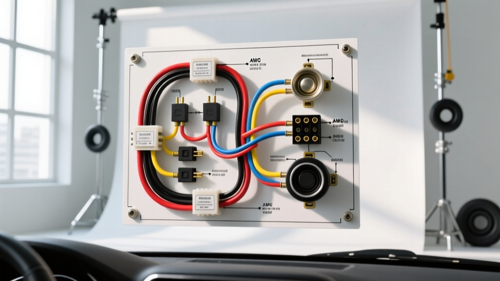
Understanding the Auto Horn Wiring Diagram and Circuit Safety
At first glance, an automotive horn circuit seems like one of the simplest electrical systems in a vehicle. However, horns are high-current inductive loads that demand precise wiring to operate reliably and safely. A flawed auto horn wiring diagram implementation doesn't just result in a silent horn; it can lead to melted steering wheel clocksprings, welded relay contacts, and severe engine bay fires. Whether you are replacing a faulty OEM unit, upgrading to high-decibel aftermarket air horns, or installing dual electromechanical disc horns, understanding the underlying electrical physics and safety protocols is mandatory.
In this guide, we break down the standard ISO relay-based horn circuit, identify the most dangerous wiring mistakes made by DIYers and inexperienced technicians, and provide actionable specifications to ensure your installation meets automotive safety standards.
The Standard Auto Horn Wiring Diagram Explained
Modern vehicles universally use a 4-pin ISO mini relay to isolate the high-current horn load from the low-current steering wheel switch. This protects the delicate clockspring (spiral cable) and body control module (BCM). Here is the standard pinout configuration you will find in almost every factory and aftermarket auto horn wiring diagram:
- Pin 30 (Common / Power Input): Receives constant 12V B+ directly from the battery via a primary fuse.
- Pin 87 (Normally Open / Output): Sends 12V to the horn's positive terminal when the relay is energized.
- Pin 86 (Coil Power / Trigger): Receives the low-current 12V signal from the horn button or BCM.
- Pin 85 (Coil Ground): Provides the ground path for the relay's internal electromagnetic coil.
When the driver presses the horn button, the circuit between Pin 86 and Pin 85 is completed. The relay coil energizes, creating a magnetic field that pulls the internal switch closed, connecting Pin 30 to Pin 87 and delivering high-current battery power to the horn.
Top 5 Common Mistakes in Horn Wiring
1. Bypassing the Relay (The Clockspring Killer)
One of the most catastrophic mistakes is wiring the horn directly to the steering wheel horn switch without a relay. Factory horn buttons and the internal clockspring are typically rated for a maximum of 2 to 3 amps. A standard single disc horn draws between 10 and 15 amps, while dual setups can pull 20 amps or more. Routing this high current through the clockspring will rapidly overheat the delicate copper traces, melting the insulation and causing a short circuit. Because the clockspring also houses the wiring for the driver's side airbag squib, melting this component introduces a severe safety hazard and results in a repair bill often exceeding $600.
2. Undersizing the Power Wire (Ignoring SAE Derating)
Many installers use 16 AWG or 18 AWG wire for the main power feed (Pin 30 to Pin 87) because it is flexible and easy to route. This is a fire hazard. According to SAE J1128 standards for low-tension primary cable, wire ampacity must be derated based on under-hood ambient temperatures, which can easily exceed 100°C (212°F) near the engine block. A 14 AWG wire rated for 15A at room temperature may only safely carry 10A in a hot engine bay. Always use a minimum of 12 AWG cross-linked polyethylene (XLPE) wire for the high-current legs of a dual-horn setup.
3. Improper Chassis Grounding at the Horn Mount
Most OEM electromechanical horns are single-wire devices; they rely on the metal mounting bracket and the vehicle's chassis to complete the ground circuit. A common failure mode occurs when an installer mounts a new horn to a painted bumper bracket, a plastic shroud, or an aluminum subframe without proper preparation. Paint, powder coating, and corrosion act as insulators. To ensure a solid ground, you must use a serrated flange nut or a star washer to bite through the paint down to bare metal. Alternatively, run a dedicated 14 AWG ground wire from the horn's negative terminal (if equipped) directly to a known clean chassis ground point.
4. Ignoring Inductive Kickback (Flyback Voltage)
Horns operate using an electromagnetic coil that vibrates a diaphragm. When the relay opens and cuts power to this coil, the collapsing magnetic field induces a massive reverse voltage spike (inductive kickback) that can exceed 100V. If your auto horn wiring diagram does not account for this, the spike will arc across the relay's internal contacts. Over time, this arcing causes pitting and eventually welds the contacts together, resulting in a horn that refuses to turn off. High-quality automotive relays, such as those documented in Littelfuse automotive relay datasheets, include an internal suppression resistor or diode to absorb this spike. Always verify your relay has built-in spike suppression when driving inductive loads.
5. Incorrect Fuse Placement and Sizing
The primary fuse for the horn circuit must be installed on the Pin 30 power wire within 18 inches of the battery positive terminal. A common mistake is placing the fuse holder near the relay or the horn itself. If the wire chafes against the radiator support or engine harness anywhere between the battery and the relay, the unfused wire will carry unlimited battery current, instantly melting the insulation and starting an electrical fire. Furthermore, do not oversize the fuse 'to prevent blowing.' If the circuit draws 18A, use a 20A or 25A ATO/ATC fuse, never a 30A or 40A fuse on 14 AWG wiring.
Horn Circuit Specification and Sizing Chart
Use the following reference table to select the correct wire gauge, fuse rating, and relay type based on your specific horn configuration. These specifications assume an under-hood ambient temperature of up to 105°C and standard copper conductors.
| Horn Configuration | Typical Current Draw | Pin 30 & 87 Wire (AWG) | Pin 85 & 86 Wire (AWG) | Primary Fuse Rating | Relay Requirement |
|---|---|---|---|---|---|
| Single OEM Disc Horn | 10A - 12A | 14 AWG | 18 AWG | 15A ATO | Standard 30A ISO Mini |
| Dual Electromechanical (e.g., Hella Supertone) | 18A - 22A | 12 AWG | 18 AWG | 25A ATO | 40A ISO Mini (w/ Resistor) |
| Heavy Duty Air Horns (w/ Compressor) | 30A - 45A (Compressor) | 10 AWG or 8 AWG | 16 AWG | 50A MIDI/AMEG | Heavy Duty Bosch-style (5-Pin) |
Safety Warnings & Best Practices for Installation
When executing your auto horn wiring diagram, adhere to these professional-grade safety protocols to ensure long-term reliability and vehicle safety:
- Disconnect the Battery: Always disconnect the negative battery terminal before cutting, stripping, or splicing any wires in the engine bay. Accidentally shorting the Pin 30 wire to ground while connected to the battery will result in immediate sparking, potential burns, and damaged wiring harnesses.
- Use Marine-Grade Heat Shrink: Never rely on electrical tape for under-hood connections. The heat and chemical exposure (oil, brake fluid, degreasers) will cause tape to unravel within months. Use dual-wall, adhesive-lined marine heat shrink tubing on all crimp connections. The internal adhesive melts and seals the connection against moisture and corrosion.
- Airbag Proximity Warning: When routing trigger wires through the steering column to test the horn button, never splice into or disturb the yellow-sheathed wiring. Yellow connectors and wire looms universally denote Supplemental Restraint System (SRS) / Airbag circuits in modern vehicles. Piercing an airbag wire can trigger accidental deployment or cause an SRS fault code.
- Protect Against Chafing: Route all wiring away from exhaust manifolds, moving suspension components, and cooling fans. Use split-loom corrugated tubing and secure the harness every 12 inches using UV-resistant zip ties or factory-style push-pin clips.
Authoritative References
For further reading on automotive electrical standards and component specifications, consult the following resources:
- SAE J1128: Low Tension Primary Cable Standard - Essential reading for understanding wire insulation temperature ratings and ampacity derating in engine compartments.
- Littelfuse Automotive Relay Datasheets - Provides detailed schematics on internal flyback diodes and suppression resistors required for inductive loads like horns.
- Hella Electromagnetic Relays in the Vehicle - A comprehensive guide on relay pinouts, contact materials, and load management for automotive accessories.