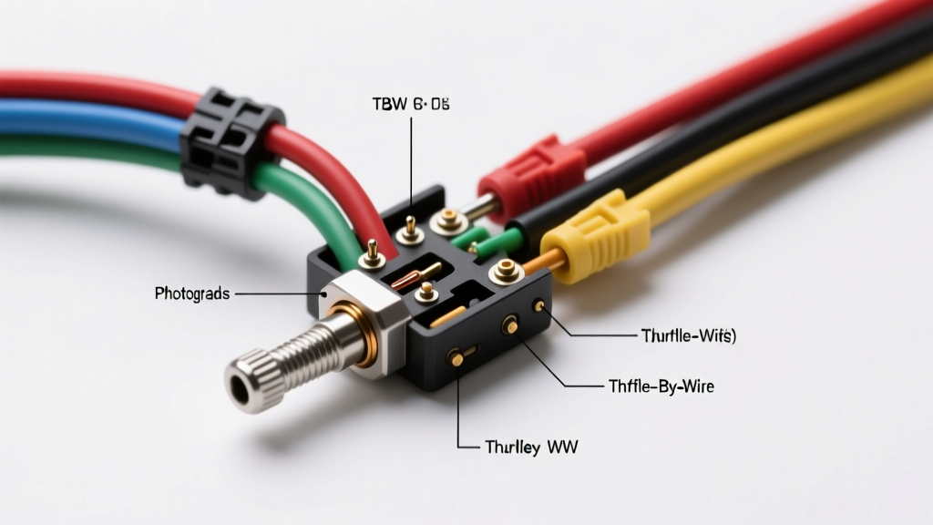
Introduction to Harley TBW Upgrades and Customization
Transitioning from mechanical throttle cables to a Throttle-By-Wire (TBW) system revolutionized the Harley-Davidson riding experience, eliminating cable stretch, reducing maintenance, and enabling precise electronic fuel injection mapping. For custom builders and enthusiasts undertaking handlebar upgrades, grip replacements, or full powertrain swaps, understanding the Harley twist grip sensor wiring diagram is absolutely critical. The Throttle Position Sensor (TPS) located in the right-hand grip assembly is not a simple variable resistor; it is a complex, dual-track Hall-effect or potentiometer module that communicates directly with the Electronic Control Module (ECM).
When executing an upgrade project—such as installing 16-inch ape hangers, swapping to an aftermarket performance throttle body, or integrating a custom ride-by-wire assembly—you cannot simply splice wires together with butt connectors and electrical tape. The ECM monitors the twist grip sensor signals in milliseconds. Any voltage drop, resistance spike, or micro-interruption caused by poor wiring practices will trigger a limp-home mode or a complete engine shutdown. This guide provides the exact pinouts, wire specifications, and integration strategies required to flawlessly execute your TBW modification project.
The Anatomy of the Harley Twist Grip Sensor (TBPS)
Unlike older cable-driven setups where the TPS was mounted on the throttle body shaft, modern Harley-Davidson TBW systems (introduced on 2008 Touring models and later expanded to Dyna and Softail platforms) utilize a Twist Grip Position Sensor (TBPS) housed directly inside the right-hand switch housing. This sensor reads the physical rotation of the grip and translates it into electronic voltage signals.
Dual Signal Redundancy Explained
To comply with stringent safety standards outlined in SAE J2952 Electronic Throttle Control protocols, the Harley TBPS utilizes dual independent signal tracks. The ECM supplies two separate 5-volt reference circuits and monitors two distinct ground circuits. This redundancy ensures that if one track fails, shorts, or loses its ground, the ECM instantly detects the discrepancy between Signal 1 and Signal 2, safely cutting power to the Electronic Throttle Control (ETC) motor to prevent a runaway throttle scenario.
Harley Twist Grip Sensor Wiring Diagram & Pinout Table
The OEM connector for the Harley twist grip sensor is a highly sealed 6-pin cavity (typically an AMP/Molex sealed series). Below is the definitive pinout reference for the most common Delphi and Bosch ECM configurations found on 2008–2015 Touring and 2016–2020 Softail/Dyna models. Note: Always verify wire colors against your specific year and model factory service manual, as Harley-Davidson occasionally updates harness color codes between production runs.
| Pin | Function | Common Wire Color (Delphi/Bosch) | AWG | Voltage Spec (Closed/WOT) |
|---|---|---|---|---|
| 1 | 5V Reference 1 | Red/White or Orange/White | 20 AWG | 4.9V - 5.1V (Constant) |
| 2 | Signal 1 (Primary) | Yellow/White or Green | 20 AWG | ~0.8V / ~4.2V |
| 3 | Sensor Ground 1 | Black/White | 20 AWG | < 0.05V |
| 4 | 5V Reference 2 | Red/Black or Orange/Black | 20 AWG | 4.9V - 5.1V (Constant) |
| 5 | Signal 2 (Redundant) | Green/White or Blue | 20 AWG | ~4.2V / ~0.8V (Inverse) |
| 6 | Sensor Ground 2 | Black/Green | 20 AWG | < 0.05V |
Understanding the Inverse Sweep Logic
Notice the voltage specifications for Signal 1 and Signal 2. As you roll the throttle from closed to Wide Open Throttle (WOT), Signal 1 sweeps upward (0.8V to 4.2V), while Signal 2 sweeps inversely downward (4.2V to 0.8V). The ECM continuously adds these two values together. If the sum deviates from the expected baseline (roughly 5.0V), the ECM flags a correlation fault. This inverse logic is a cornerstone of Bosch Mobility Throttle-By-Wire safety architectures.
Step-by-Step TBW Throttle Upgrade Integration
When installing extended reach handlebars (like 14-inch ape hangers) or custom hand controls, the OEM TBW harness will be too short. You must extend the 6-circuit harness. Here is the professional methodology for executing this modification without degrading signal integrity.
1. Select the Correct Wire Specification
Do not use standard PVC primary wire. You must use 20 AWG TXL (Thin-wall Cross-Linked) or GXL automotive wire. TXL wire features cross-linked polyethylene insulation that withstands engine bay temperatures up to 125°C (257°F) and resists the harsh chemicals found in motorcycle cleaning solvents. According to TXL wire specification charts, 20 AWG provides optimal flexibility for routing through tight steering neck bearings while maintaining the necessary current capacity for 5V reference signals.
2. Repinning vs. Solder Splicing
While soldering with marine-grade adhesive heat shrink is acceptable in a pinch, the gold standard for TBW harness extensions is repinning. Cut the OEM harness near the connector, extract the terminals using the appropriate micro-terminal removal tool, and crimp new sealed terminals onto your extended TXL wires. Use a ratcheting crimp tool designed for sealed weather-pack terminals (such as the Delphi Packard crimp tool). This ensures a gas-tight connection that will not suffer from vibration-induced resistance spikes near the steering stem.
3. Routing and Strain Relief
Route the extended TBW harness inside the handlebars if they are internally wired, or secure them with split-loom tubing and UV-resistant zip ties. Critical Warning: You must leave exactly enough slack in the harness to allow the front forks to compress fully and the handlebars to turn lock-to-lock without pulling on the grip sensor connector. A pulled connector will cause microscopic pin separation, resulting in intermittent P2135 throttle correlation codes.
Diagnostic Trouble Codes (DTCs) & Signal Validation
During your upgrade project, if the ECM detects an anomaly in the twist grip sensor circuit, it will illuminate the Check Engine Light and default to a restrictive limp mode. Familiarize yourself with these common TBW DTCs:
- P0121 (Throttle Position Sensor 1 Performance): Signal 1 is out of the expected voltage range or dropping out entirely.
- P0221 (Throttle Position Sensor 2 Performance): Signal 2 is failing to track inversely with Signal 1.
- P2135 (Throttle/Pedal Position Sensor A/B Voltage Correlation): The ECM sees that Signal 1 and Signal 2 do not mathematically align. Often caused by a shared ground failure or a 5V reference short.
- P0122 / P0222 (Circuit Low Voltage): Usually indicates a short to ground on the signal wire or an open 5V reference circuit.
- P0123 / P0223 (Circuit High Voltage): Typically points to an open ground circuit at the grip connector, causing the signal wire to float high.
Why a Multimeter is Not Enough: The Oscilloscope Sweep Test
Many DIY builders attempt to diagnose TBW issues with a standard digital multimeter (DMM). While a DMM is fine for checking the static 5V reference and ground continuity, it is entirely inadequate for testing the signal sweep. A multimeter samples voltage too slowly to catch micro-dropouts caused by a chafed wire or a failing Hall-effect sensor track.
For a proper diagnostic validation, connect a dual-channel automotive oscilloscope to Pin 2 (Signal 1) and Pin 5 (Signal 2). Slowly roll the throttle grip from closed to WOT. On the scope screen, you should see two perfectly smooth, continuous sine-like waves moving in opposite directions. If you see any vertical spikes, flat spots, or noise fuzz in the waveform, the twist grip sensor is internally damaged or the harness has a high-resistance fault that the DMM missed.
Expert Troubleshooting: Real-World Failure Modes in Custom Builds
When modifying the front-end controls, builders frequently encounter issues that mimic a bad sensor but are actually installation errors. Here are the most common real-world failure modes:
- Steering Neck Chafing: If the TBW harness is routed too tightly against the steering neck without a Teflon sleeve or protective loom, the constant left-to-right steering motion will wear through the 20 AWG TXL insulation. Because all 6 wires are bundled together, Signal 1 and the 5V Reference often short together, instantly frying the internal ECM driver circuit.
- Moisture Ingress in Aftermarket Housings: Many aftermarket custom switch housings lack the OEM-level silicone potting and O-ring seals. Rain and motorcycle wash water infiltrate the grip cavity, bridging the gap between the 5V reference and the ground pins. This causes a P2135 code that only appears when it rains.
- Aftermarket Grip Sleeve Interference: Installing thick, aftermarket heated grips or custom rubber sleeves can sometimes bind against the switch housing. This physical binding creates friction, preventing the TBW return spring from snapping the throttle fully closed, leading to a high-idle or a 'Throttle Not Closed' DTC.
By adhering to the precise Harley twist grip sensor wiring diagram, utilizing TXL cross-linked wiring, and validating your signals with an oscilloscope, your TBW upgrade project will deliver factory-level reliability and seamless throttle response on the open road.