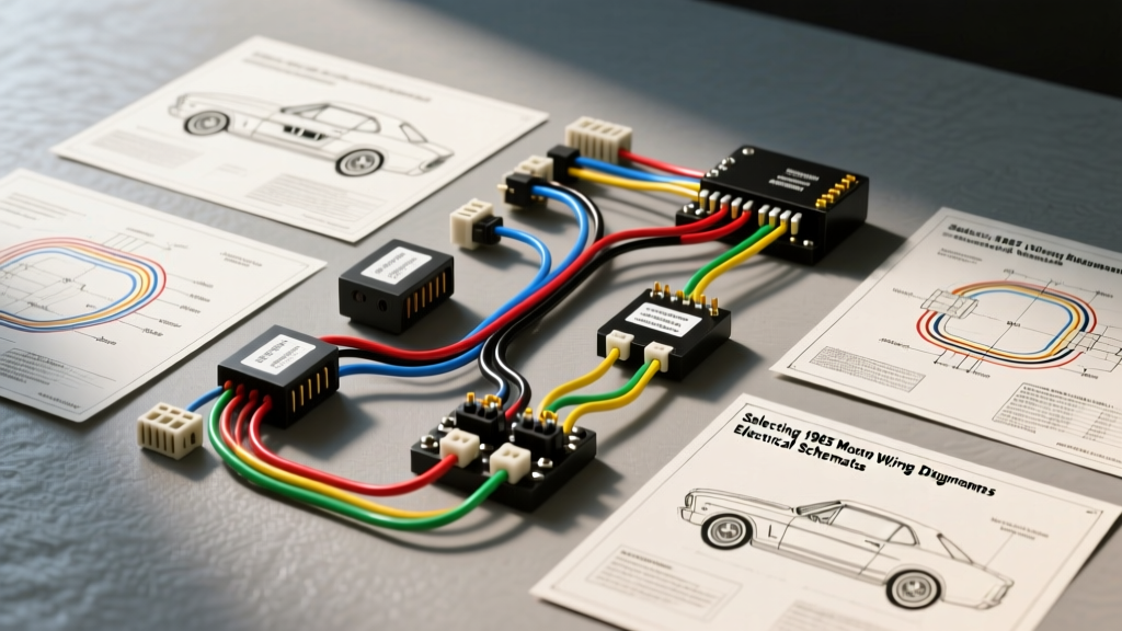
Navigating 1965 Mustang Wiring Diagrams & Electrical Schematics
The first-generation Ford Mustang is an automotive icon, but its original electrical system was never designed to handle the demands of modern driving, let alone survive six decades of heat, vibration, and previous owner modifications. When sourcing 1965 Mustang wiring diagrams electrical schematics, restorers and mechanics must navigate a complex web of mid-year production changes, obsolete connector types, and degraded insulation. Whether you are performing a concours-correct restoration or building a resto-mod with a high-output alternator and electric cooling fans, selecting the right schematic package and reproduction harness is critical to preventing voltage drops and electrical fires.
OEM Assembly Manuals vs. Aftermarket Schematic Packages
Understanding the lineage of your schematic is just as important as the wiring itself. There are two primary categories of 1965 Mustang wiring diagrams available to restorers today:
Ford OEM Assembly Line Schematics
Original Ford Master Parts and Assembly Line manuals are drafted in black-and-white line art. They utilize Ford-specific electrical symbols and focus heavily on physical routing, harness taping, and clip locations. While invaluable for judges at Mustang Club of America (MCA) concours events, these diagrams lack color-coding and can be incredibly difficult to trace for a mechanic troubleshooting a short circuit in a dimly lit garage.
Modern Aftermarket Restoration Schematics
Companies like American Autowire and M&H Electric Fabricators provide redrawn, color-coded schematics. These diagrams translate the original Ford engineering blueprints into modern, standardized IEEE electrical symbols. They explicitly map out wire color tracers, inline fuse locations, and bulkhead connector pinouts, making them vastly superior for hands-on troubleshooting and custom harness fabrication.
Critical 1965 Mustang Electrical Specifications
When reading your 1965 Mustang wiring diagrams, cross-referencing the original wire colors and American Wire Gauge (AWG) sizes against the SAE J1128 Low Tension Primary Cable Standard is essential for safety. Below is a reference chart for the core circuits of the '65 Mustang chassis and dash harnesses.
| Circuit Function | OEM Wire Color Code | AWG Size | Connector / Routing Note |
|---|---|---|---|
| Main Battery to Ammeter | Black with Yellow Tracer | 10 AWG | Ring terminal at solenoid; routes through engine bay loom. |
| Headlight Switch Feed | Black with Yellow Tracer | 12 AWG | Molded 3-pin plug at the back of the dash switch. |
| Right Front Turn Signal | Green with White Tracer | 16 AWG | Push-on bullet connector; routes through radiator support. |
| Left Front Turn Signal | White with Black Tracer | 16 AWG | Push-on bullet connector; routes through radiator support. |
| Taillight Feed (Right) | Green with Orange Tracer | 18 AWG | Passes through under-floor rubber grommet near rear axle. |
| Ignition Switch to Coil (+) | Red with Green Tracer | 16 AWG (Resistance) | Integrated resistance wire (1.35 ohms); replaces external ballast. |
Expert Note: The Red/Green wire feeding the ignition coil is a specialized resistance wire. Unlike Chrysler products of the era that used a separate ceramic ballast resistor, Ford integrated the resistance directly into the harness wire to drop the 14V system voltage down to the 9V required by the Autolite points-style ignition coil. Replacing this with standard 16 AWG copper wire will overheat and destroy your coil.
The Mid-Year Split: Generator vs. Alternator Schematics
The most confusing aspect of 1965 Mustang wiring diagrams electrical schematics is the mid-year transition from a DC generator to the 1G alternator. Your vehicle's build date dictates which schematic you must use.
- Early Build (Pre-March 1965): Equipped with a generator and a mechanical voltage regulator mounted on the driver's side inner fender. The schematic will show a 4-pin regulator plug (Battery, Armature, Field, Ground) and a generator warning light circuit.
- Late Build (March 1965 Onward): Ford transitioned to the Motorola-designed 1G alternator. The schematics for these vehicles feature a 3-wire alternator plug (Stator, Field, Ground) and an integrated solid-state or simplified mechanical regulator. The dash warning light circuit is also wired differently, utilizing the stator terminal to extinguish the 'GEN' light once the alternator begins producing AC voltage.
Attempting to wire a late-model 1G alternator using an early generator schematic will result in a parasitic battery drain and a dead battery overnight, as the field circuit will remain energized when the key is off.
Top Reproduction Wiring Harness Brands Compared
Once you have the correct schematics, selecting the physical harness is the next step. Here is a comparison of the top manufacturers in the classic Ford market.
M&H Electric Fabricators (The OEM Purist Choice)
M&H Electric Fabricators is the gold standard for concours restorations. They use the exact same cross-link polyethylene (XLPE) wire insulation and cloth-braided loom wrappers as the original Ford San Jose and Dearborn assembly lines. Their harnesses include the correct Ford script printed on the wires and utilize original-style Packard Electric 56-series terminals. However, they retain the original glass SFE fuses and low-amp headlight circuits, making them unsuitable for high-draw modern accessories.
American Autowire (The Resto-Mod Choice)
The American Autowire Classic Update Series is designed for drivers who want modern reliability. Their '65 Mustang kit completely eliminates the under-dash glass fuse block, replacing it with a modern ATO/ATC blade fuse panel. Crucially, they upgrade the main battery feed and headlight circuits to handle higher amperage, and they include a heavy-duty alternator charge wire (typically 8 AWG or 6 AWG) to support 100-amp 1-wire or 3-wire alternator upgrades. The trade-off is a loss of concours correctness, as the wire colors and fuse block location deviate from OEM blueprints.
Painless Performance (The Custom Chassis Choice)
Painless offers universal and model-specific chassis harnesses that are heavily relay-driven. If you are adding HID headlights, electric fuel pumps, and aftermarket A/C, Painless schematics provide dedicated relay triggers and heavy-gauge direct battery feeds. Their kits require more fabrication and terminal crimping than plug-and-play OEM repros, but they offer the highest degree of circuit protection for heavily modified builds.
Common '65 Mustang Wiring Failure Modes & Troubleshooting
Even with a brand-new harness and pristine schematics, the '65 Mustang has several inherent electrical design flaws that require attention during reassembly.
Headlight Switch Thermal Breaker Tripping
The original '65 headlight switch contains an internal thermal circuit breaker. As the 50-year-old headlight wiring harness degrades, resistance increases. This resistance generates heat at the switch, causing the internal thermal breaker to trip and shut off the headlights while driving. The Fix: When using an OEM-style harness, install a 30-amp Bosch-style relay under the hood to handle the headlight current load, using the original headlight switch only as a low-amp trigger signal.
Steering Column Turn Signal Cam Degradation
The turn signal switch on the '65 Mustang is located inside the steering column and relies on a plastic cam and copper contact sliders. Over time, the plastic cam cracks, and the copper contacts lose tension. This manifests as turn signals that work when the lever is pushed up (Right), but fail when pushed down (Left), or hazard flashers that only illuminate three out of four bulbs. The schematics will show the multi-wire plug at the base of the column; always test for continuity at this plug before tearing apart the steering column.
Firewall Bulkhead Connector Corrosion
The main chassis harness passes through the firewall via a multi-pin bulkhead connector. In OEM designs, this plug is exposed to engine bay heat and moisture, leading to terminal oxidation and voltage drops to the instrument cluster and taillights. When installing a new harness, apply a generous amount of dielectric grease (such as Permatex or DeoxIT) to every male and female terminal in the bulkhead connector before mating the halves together.
Final Thoughts on Schematic Selection
Successfully rewiring a classic Ford requires more than just plugging in connectors; it requires a deep understanding of the engineering logic behind the 1965 Mustang wiring diagrams electrical schematics. By matching your schematic source and harness brand to your specific build goals—whether that means preserving the exact resistance wire for a date-coded Autolite coil or upgrading to blade fuses for a modern stereo system—you ensure that your Mustang remains both a reliable driver and a safe vehicle for decades to come.