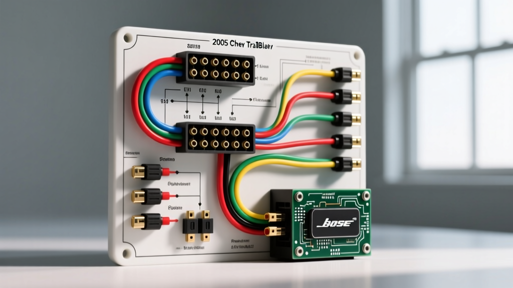
2005 Chevy TrailBlazer Audio Architecture Overview
The 2005 Chevrolet TrailBlazer, built on General Motors' GMT360 platform, features a unique audio architecture heavily reliant on the GM Class 2 Serial Data Bus (SAE J1850 VPW). When consulting a 2005 Chevy TrailBlazer stereo wiring diagram, technicians and DIY installers must understand that the factory Delco head unit acts as a gateway module for vehicle chimes, OnStar telematics, and steering wheel controls (SWC). Replacing the OEM radio with an aftermarket double-DIN unit requires more than just splicing power and speaker wires; it requires managing data bus termination and understanding the Body Control Module (BCM) wake-up signals.
This comprehensive walkthrough details the exact pinouts, wire color codes, AWG specifications, and integration requirements for both the base audio system and the premium Bose amplifier setup found in the 2005 TrailBlazer and TrailBlazer EXT.
Main Radio Harness Pinout (16-Pin Connector C1)
The primary power, ground, and data connections are routed through a 16-pin Delphi connector (Connector C1). The OEM wiring utilizes cross-linked polyethylene (XLPE) insulated copper, typically rated for 105°C. Below is the definitive pinout for the C1 harness.
| Pin | Wire Color | Function | AWG / Spec |
|---|---|---|---|
| 1 | Yellow | Battery 12V+ (Constant) | 18 AWG (Upgradable to 12 AWG) |
| 2 | Brown | Ignition 12V+ (Switched / BCM Run) | 18 AWG |
| 3 | Black/White | Chassis Ground | 18 AWG (Upgradable to 12 AWG) |
| 4 | Brown/White | Panel Illumination (PWM Dimming) | 20 AWG |
| 5 | Pink | Amplifier Turn-On (Remote) | 18 AWG |
| 6 | Not Used | Empty Cavity | N/A |
| 7 | Not Used | Empty Cavity | N/A |
| 8 | Not Used | Empty Cavity | N/A |
| 9 | Not Used | Empty Cavity | N/A |
| 10 | Dark Green | Class 2 Serial Data Bus (VPW) | 20 AWG Shielded |
| 11 | Light Green | Right Steering Wheel Control (SWC) | 20 AWG |
| 12 | Light Blue/Black | Left Steering Wheel Control (SWC) | 20 AWG |
| 13 | Tan/White | Mute / OnStar Audio Override | 20 AWG |
| 14 | Purple/White | Vehicle Speed Sensor (VSS) Signal | 20 AWG |
| 15 | Not Used | Empty Cavity | N/A |
| 16 | Orange/Black | Accessory Delay (RAP - Retained Accessory Power) | 18 AWG |
Expert Note: The 2005 TrailBlazer uses Pulse Width Modulation (PWM) for dash illumination on Pin 4. Aftermarket stereos expecting a simple 12V illumination trigger may exhibit flickering. Use a 12V PWM-to-DC converter relay if your aftermarket head unit lacks PWM dimming compatibility.
Speaker Output Harness (8-Pin Connector C2)
The speaker outputs are isolated on an 8-pin connector. The base audio system utilizes 4-ohm paper-cone speakers, while the Bose system utilizes 2-ohm neodymium drivers. Feeding 2-ohm Bose speakers with a standard 4-ohm aftermarket head unit amplifier will cause the head unit's internal thermal protection to trip, resulting in audio clipping or complete shutdown.
| Pin | Location | Polarity | Wire Color |
|---|---|---|---|
| 1 | Left Front | Positive (+) | Tan |
| 2 | Left Front | Negative (-) | Gray |
| 3 | Right Front | Positive (+) | Light Green |
| 4 | Right Front | Negative (-) | Dark Green |
| 5 | Left Rear | Positive (+) | Brown |
| 6 | Left Rear | Negative (-) | Yellow |
| 7 | Right Rear | Positive (+) | Dark Blue |
| 8 | Right Rear | Negative (-) | Light Blue |
Bose Premium Amplifier Integration & Bypass
If your 2005 TrailBlazer is equipped with the Bose premium audio package (RPO UQ3), the factory head unit outputs low-level (RCA equivalent) signals to an external amplifier located under the center console, behind the HVAC controls. The amplifier then drives the 2-ohm speakers.
Option A: Bypassing the Bose Amplifier
To bypass the Bose amp and run new 16 AWG speaker wire directly from an aftermarket head unit to the door speakers, you must remove the door panels and bypass the factory amp harness. This yields the cleanest audio signal and eliminates the aging OEM amplifier's inherent noise floor. Ensure you route the new 16 AWG wire through the factory rubber door jamb boots to prevent moisture ingress and short circuits against the A-pillar.
Option B: Retaining the Bose Amplifier
If retaining the Bose amp, you must use a line output converter (LOC) or an active integration module like the Metra GMOS-01 or Axxess GMOS-04. These modules intercept the high-level or low-level signals, provide a 12V remote turn-on signal to the Bose amp's Pink wire (Pin 5), and most importantly, retain the GMT360 platform's critical door chimes and OnStar audio routing.
Class 2 Data Bus, SWC, and OnStar Telematics
The GMT360 platform utilizes the SAE J1850 VPW (Variable Pulse Width) Class 2 data bus for module communication. Pin 10 (Dark Green) on the C1 connector is the data line. Unlike older analog systems, steering wheel audio controls in the 2005 TrailBlazer do not use simple resistance ladder networks; they communicate via the data bus.
To retain steering wheel controls with an aftermarket stereo, you must install a digital interface such as the PAC SWI-RC or Axxess ASWC-1. These modules 'sniff' the Class 2 data bus, decode the GM steering wheel button presses, and translate them into the proprietary IR or hardwired commands required by Pioneer, Kenwood, Alpine, or Sony head units.
OnStar Integration: If the vehicle is equipped with OnStar, the audio is routed through the head unit. Pulling the OEM radio breaks the OnStar audio path. A GMOS integration module is strictly required to multiplex the OnStar audio signal into the aftermarket stereo's auxiliary or front speaker inputs when an OnStar call is initiated.
Power Wire Upgrades & SAE Standards
The OEM Yellow (Constant 12V) and Black/White (Ground) wires are 18 AWG, which is sufficient for the factory Delco unit's 7W x 4 RMS output. However, modern aftermarket head units frequently output 14W to 22W x 4 RMS, or feature built-in class-D amplifiers pushing 45W x 4 RMS. According to SAE J1128 standards for automotive low-tension primary cable, 18 AWG wire will experience significant voltage drop and heat generation at continuous draws exceeding 10 amps.
Upgrade Procedure:
- Cut the OEM Yellow and Black/White wires 4 inches from the factory plug.
- Splice in 12 AWG stranded oxygen-free copper (OFC) wire using adhesive-lined heat shrink butt connectors.
- Route the new 12 AWG Yellow wire directly to the battery with an inline 15A ATC fuse within 18 inches of the positive terminal.
- Ground the new 12 AWG Black wire directly to a bare metal bolt on the chassis cross-brace under the dash, sanding away any paint or powder coating to ensure < 0.05 ohms of resistance.
Diagnostic Decision Tree: Common Audio Faults
When troubleshooting wiring faults post-installation, follow this diagnostic sequence:
- Symptom: Head unit powers on, but no audio and no door chimes.
Cause: The BCM has not registered the radio wake-up signal, or the data bus is terminated.
Fix: Verify Pin 10 (Dark Green) is connected to the integration module. Check for 12V on Pin 2 (Brown) during the 'Run' cycle. If using a GMOS module, ensure the module's diagnostic LED is flashing, indicating active Class 2 communication. - Symptom: Alternator whine that pitches up and down with engine RPM.
Cause: Ground loop induced by shared ground paths between the BCM and the aftermarket head unit.
Fix: Isolate the head unit ground. Do not ground the stereo to the same bolt as the BCM or HVAC controls. Run a dedicated 12 AWG ground to the main chassis kick-panel ground stud. - Symptom: Radio turns off immediately after engine shutoff, ignoring Retained Accessory Power (RAP).
Cause: Ignition wire tied to constant 12V, or RAP circuit (Pin 16) not utilized.
Fix: Ensure Pin 2 (Brown) is connected to the aftermarket head unit's Red (Ignition) wire, and Pin 1 (Yellow) is connected to the Yellow (Constant) wire. The BCM cuts power to Pin 2 when the driver's door is opened, triggering the head unit's shut-off sequence.
For further OEM schematic verification and module programming parameters, technicians should consult the General Motors Service Information portal via Helm Incorporated or reference the Crutchfield vehicle-specific fit database for verified dash kit tolerances and antenna adapter requirements (typically a standard GM Motorola to aftermarket adapter, though deep-cavity GMT360 dashes often require a 90-degree antenna adapter to prevent stress on the RF port).