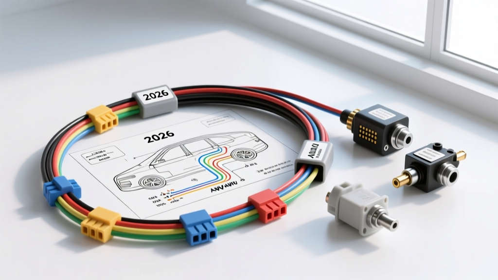
The Evolution of the 2026 Hood Circuit Wiring Diagram
As automotive platforms transition into the 2026 model year, the traditional mechanical hood release cable has been almost entirely replaced by electronic hood release (EHR) systems. Driven by the need for active aerodynamics, EV front-trunk (frunk) integration, and enhanced pedestrian safety, the modern hood circuit wiring diagram 2026 relies heavily on Body Control Module (BCM) logic, PWM (Pulse Width Modulation) motor control, and CAN-bus status reporting. For automotive technicians, custom fabricators, and EV conversion specialists, understanding how to select, wire, and integrate these hood latch actuators is critical. This guide compares the leading actuator products on the market and provides a comprehensive wiring schematic breakdown to ensure safe, FMVSS-compliant installations.
Product Comparison: Hood Latch Actuators & Release Kits
When repairing a damaged harness or retrofitting an electronic release onto a custom build, selecting the correct actuator is paramount. Below is a technical comparison of the three primary hood release products used in modern applications.
1. OEM Dual-Stage E-Latch (Bosch / Kiekert Platforms)
Used in most 2026 OEM EV and luxury ICE platforms, this assembly integrates a DC micro-motor, a primary latch pawl, and a secondary safety catch into a single sealed housing. It features an internal Hall-effect sensor for precise pawl positioning.
- Pros: Fully compliant with FMVSS 113 Hood Latch Systems regulations; includes redundant secondary latch; provides CAN-bus feedback to the BCM.
- Cons: Requires proprietary BCM programming and security gateway access; high replacement cost.
- Best For: OEM restorations, late-model collision repair, and warranty-compliant diagnostics.
2. Aftermarket 12V Linear Solenoid Kit (50lb Pull)
A staple in street rod and custom car builds, this product uses a simple electromagnetic coil to pull a plunger, releasing the mechanical latch. It lacks a secondary safety catch and operates on a simple 12V momentary ground trigger.
- Pros: Extremely simple wiring (2-wire setup); no BCM programming required; universally compatible with momentary push-buttons.
- Cons: High inrush current (up to 18A); lacks secondary latch safety; coil generates massive inductive voltage spikes that can fry solid-state relays if not protected by a flyback diode.
- Best For: Off-road rigs, show cars, and custom frunk builds where FMVSS compliance is not a legal requirement.
3. Hall-Effect Micro-Switch Retrofit Module
Instead of a motor, this product replaces the mechanical plunger-style hood ajar switch with a non-contact Hall-effect sensor. It is often paired with an OEM E-Latch to provide waterproof, corrosion-proof status reporting to the BCM.
- Pros: Zero mechanical wear; IP69K waterproof rating; immune to vibration-induced false 'hood open' warnings.
- Cons: Requires a 5V reference and a pull-up resistor on the signal circuit.
- Best For: High-vibration environments, off-road racing, and marine-adjacent vehicle builds.
2026 Hood Circuit Wiring Diagram Breakdown
The standard 2026 OEM hood latch connector utilizes a 4-pin sealed interface, typically an TE Connectivity AMP Superseal 1.5 or Aptiv Metri-Pack 280 series housing. The BCM controls the motor via a high-side driver and monitors the latch position via a low-current signal return.
Pinout Configuration & Circuit Functions
- Pin 1 (Motor Control +): Receives a 12V PWM signal from the BCM to actuate the DC motor. The duty cycle varies based on pawl resistance.
- Pin 2 (Motor Ground -): Dedicated chassis ground. Must be grounded to a clean, unpainted metal surface within 18 inches of the latch to prevent voltage drop.
- Pin 3 (Primary Ajar Signal): 5V reference signal from the BCM. Drops to 0V when the primary latch is disengaged (hood open).
- Pin 4 (Secondary Latch Status): Independent circuit for the safety catch. If this circuit reads 'open' while Pin 3 reads 'closed', the BCM triggers a 'Hood Ajar' warning on the dash and disables remote-start functions.
Wire Gauge & Connector Selection Chart
Proper wire sizing is critical. Using undersized wire for the motor circuit will result in a voltage drop, causing the BCM to log a DTC (Diagnostic Trouble Code) such as B108E: Hood Release Motor Circuit Performance. All under-hood wiring must meet SAE J1128 standards for high-temperature, low-tension primary cable, utilizing XLPE (Cross-Linked Polyethylene) insulation rated for 150°C.
| Circuit Function | OEM Wire Color | AWG Size | Terminal Type | Max Voltage Drop |
|---|---|---|---|---|
| Motor Control (+) | RED / WHT | 14 AWG | Metri-Pack 280 Female | < 0.2V |
| Motor Ground (-) | BLK | 14 AWG | Metri-Pack 280 Female | < 0.1V |
| Primary Ajar Signal | GRY / BLK | 20 AWG | Metri-Pack 150 Female | N/A (Digital) |
| Secondary Latch Status | BRN / WHT | 20 AWG | Metri-Pack 150 Female | N/A (Digital) |
BCM Programming & CAN-Bus Integration
One of the most common pitfalls when installing an OEM 2026 hood latch on a custom or swapped platform is the BCM's expectation of motor feedback. Modern BCMs monitor the current draw (amperage spike) when the motor hits the mechanical hard-stop of the latch. If you substitute an OEM E-Latch with a simple aftermarket solenoid, the BCM will not detect this current spike and will assume the motor has failed, throwing a hard code and disabling the remote-release feature.
The Workaround: If integrating a basic solenoid into a modern CAN-bus network, you must wire a 10-ohm, 5W power resistor in parallel with the solenoid coil, alongside a 1N4007 flyback diode to absorb inductive kickback. This tricks the BCM's high-side driver into reading the expected resistance profile, preventing the B108E DTC while protecting the transistor from voltage spikes.
Advanced Troubleshooting Decision Tree
When diagnosing a faulty hood release circuit, follow this logical sequence before replacing the latch assembly:
- Symptom: Hood does not release via interior switch or key fob.
Test: Connect a digital multimeter (DMM) to Pin 1 and Pin 2 at the latch connector. Press the release button. Do you see a 12V PWM pulse?
Fix: If YES, the latch motor is seized (replace assembly). If NO, check BCM fuse and relay. - Symptom: Dash displays 'Hood Open' but hood is physically closed.
Test: Back-probe Pin 3 (GRY/BLK). With the hood closed, voltage should read ~5V. If it reads 0V, the internal micro-switch is shorted, or the wire is chafed against the radiator support.
Fix: Inspect the harness where it passes through the rubber grommet near the hood hinge—a common failure point due to repetitive flexing. - Symptom: U0140-00 (Lost Communication with BCM) accompanies hood circuit faults.
Test: The hood circuit itself is likely fine. Check the CAN-H and CAN-L twisted pair at the BCM X2 connector for proper 60-ohm termination resistance and 2.5V / 2.5V bias.
Final Installation Best Practices
Always use a dedicated crimping tool (such as the Delphi 12094428 or equivalent) for Metri-Pack terminals. Soldering wires directly to terminals in high-vibration under-hood environments leads to capillary action wicking flux into the connector housing, eventually causing galvanic corrosion and high-resistance faults. Apply a dielectric silicone grease (like Nyogel 760G) to the connector cavity before mating to ensure long-term IP67 waterproof integrity.