The Case for Automotive-Grade Power Wheels Rewiring
While Power Wheels are classified as children's toys, the electrical principles governing their 12V DC traction motors are identical to those in full-size automotive accessory circuits and light EV conversions. Factory OEM wiring harnesses are notoriously under-engineered to meet a low price point. They typically rely on 16 AWG or 18 AWG stranded wire, direct-load foot pedals, and undersized spade connectors. When a 12V 550-size motor stalls or climbs an incline, it can draw upwards of 25 to 30 amps. Pushing 30A through 16 AWG wire and cheap brass switch contacts results in severe voltage drop, thermal runaway, and melted plastic housings.
Upgrading a Power Wheels chassis using a proper automotive power wheels wiring diagram requires integrating relays, ATO blade fuses, and SAE-compliant wiring. This guide provides a comprehensive cost and tool requirements analysis for fabricating a reliable, high-current 12V harness that mirrors professional automotive electrical standards.
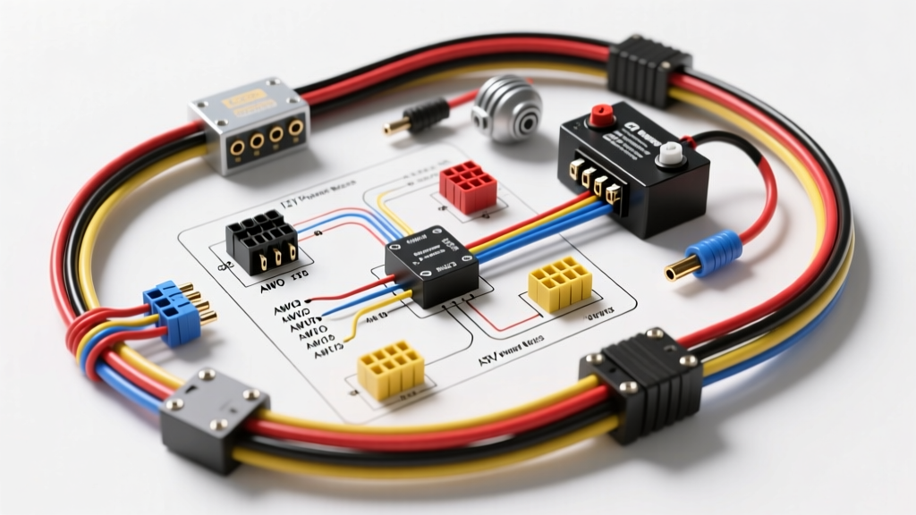
The Upgraded 12V Power Wheels Wiring Diagram
The core philosophy of this upgraded schematic is remote switching. Instead of routing the full 25A+ motor load through the child's foot pedal or dashboard shifter, the switch only carries the low-current trigger signal (less than 1A) to a high-amperage relay. The relay then handles the heavy current directly from the battery to the motors.
Schematic Flow & Routing
- Primary Power: 12V SLA (Sealed Lead Acid) Battery positive terminal routes to an ATO fuse holder (20A or 25A), then to Pin 30 of a Bosch-style SPST relay.
- Load Output: Pin 87 of the relay routes directly to the positive terminals of the drive motors.
- Trigger Circuit: The OEM foot pedal or forward/reverse shifter is rewired to interrupt a low-current 12V signal. This signal feeds Pin 86 of the relay.
- Grounding: Pin 85 of the relay grounds to the chassis or battery negative. The motor negative terminals also return to the battery negative via a high-current shunt or heavy-gauge ground bus.
For a detailed breakdown of standard automotive relay configurations, the 12V Planet Relay Guide is an industry-standard reference for ISO mini relay pinouts and load management.
Tool Requirements Analysis: What You Actually Need
Fabricating a harness that will survive the vibration, moisture, and thermal cycling of outdoor use requires specialized tools. Cheap hardware-store pliers will not suffice for high-current automotive terminals.
1. Ratcheting Terminal Crimper (Estimated Cost: $35 - $55)
High-current connections rely on cold-weld deformation. If you are upgrading to Anderson Powerpole (APP) connectors or Deutsch DT connectors, a ratcheting crimper is non-negotiable. The ratchet mechanism ensures the crimp cycle is fully completed before releasing, applying the exact tonnage required to compress a 10 AWG copper strand into a stamped brass contact without crushing it. Recommendation: IWISS SN-48B or Glarks ratcheting crimper set with interchangeable dies.
2. Precision Wire Strippers (Estimated Cost: $40 - $60)
Nicking the copper strands during stripping reduces the wire's cross-sectional area, creating a localized high-resistance hot spot. Automotive-grade strippers use precision-machined shear blades that score the insulation without touching the copper. Recommendation: Knipex 12 62 180 or Titan 11240. The ROI on preventing a single melted harness justifies the cost.
3. Digital Multimeter with Amp Clamp (Estimated Cost: $60 - $150)
You cannot diagnose voltage drop or verify motor stall current without a quality DMM. A multimeter allows you to measure the voltage at the battery versus the voltage at the motor terminals under load. If you see 12.6V at the battery but only 9.5V at the motor while driving, your wire gauge or crimps are inadequate. Recommendation: AstroAI DM6000AR or Fluke 115.
4. Adhesive Heat Shrink & Heat Gun (Estimated Cost: $25)
Standard electrical tape degrades in UV light and peels off in summer heat. Dual-wall adhesive heat shrink (containing an inner layer of hot-melt glue) provides a waterproof, vibration-proof seal over ring terminals and butt splices, meeting SAE environmental standards.
Bill of Materials (BOM) & Cost Breakdown
The following BOM outlines the cost to fabricate a complete, automotive-grade dual-motor harness for a standard 12V Power Wheels vehicle. Prices reflect premium automotive electrical suppliers.
| Component | Specification | Qty | Est. Cost |
|---|---|---|---|
| Primary Wire | 10 AWG SAE J1128 GXL (Red/Black) | 15 ft | $18.00 |
| Trigger Wire | 16 AWG SAE GXL (Yellow/Blue) | 10 ft | $6.00 |
| Relay | Bosch-Style 12V 40A SPST (ISO Mini) | 2 | $14.00 |
| Relay Sockets | 5-Pin Pigtail with 12 AWG leads | 2 | $12.00 |
| Overcurrent Protection | ATO/ATC Inline Fuse Holder + 25A Blade | 2 | $10.00 |
| Connectors (Battery) | Anderson Powerpole 45A (APP) | 1 Set | $8.00 |
| Connectors (Motor) | Deutsch DT 2-Pin Plugs & Receptacles | 2 Sets | $16.00 |
| Insulation | Dual-Wall Adhesive Heat Shrink Assortment | 1 Kit | $15.00 |
| Total Estimated Cost | $99.00 |
Cost Analysis: While an OEM replacement harness costs roughly $15 to $20, it is destined to fail within 12 months under heavy use. The $99 investment in an automotive-grade harness yields a permanent solution, eliminates the fire hazard of melting foot pedals, and allows for future battery upgrades (e.g., swapping the 12V SLA for a 12V LiFePO4 pack).
Technical Specifications: Wire Gauge & Pinout Data
Adhering to SAE J1128 standards for low-tension primary cable ensures the wire insulation can withstand under-hood (or in this case, under-chassis) temperatures up to 125°C. GXL (General Cross-Linked) wire features a thinner insulation wall than standard TXL, allowing for tighter routing in the cramped plastic chassis of a Power Wheels vehicle while maintaining high thermal resistance.
Relay Pinout & Wire Color Code Chart
| Relay Pin | Function | Wire Color | AWG Size | Connection Point |
|---|---|---|---|---|
| 30 | Common (Power In) | Red | 10 AWG | ATO Fuse Holder (Battery Side) |
| 87 | Normally Open (Load Out) | Red | 10 AWG | Motor Positive / Deutsch Plug |
| 86 | Coil Trigger (+) | Yellow | 16 AWG | OEM Shifter / Foot Pedal Output |
| 85 | Coil Ground (-) | Black | 16 AWG | Chassis Ground / Battery Negative |
| 87a | Normally Closed | N/A | N/A | Unused (Trim and heat-shrink) |
Common Failure Modes & Troubleshooting
Even with a perfect schematic, improper execution leads to electrical faults. Use the following diagnostic tree to troubleshoot custom Power Wheels harnesses:
- Symptom: Vehicle moves sluggishly, motors sound strained.
Cause: Severe voltage drop.
Fix: Perform a loaded voltage drop test. Place the DMM leads across the battery positive and motor positive while the wheels are blocked (stall condition). A reading higher than 0.5V indicates a bad crimp, an undersized wire gauge, or a corroded Anderson Powerpole contact. Re-crimp using a ratcheting tool. - Symptom: Relay clicks rapidly (chatters) when pedal is pressed.
Cause: Voltage starvation at the trigger coil.
Fix: The OEM foot pedal switch is likely degraded, offering high resistance to the 16 AWG trigger wire. Clean the switch contacts with electrical contact cleaner or bypass the OEM switch with a heavy-duty microswitch. - Symptom: Anderson Powerpole connector melts during extended use.
Cause: Improper crimp or mismatched gauge.
Fix: Verify you are using the correct APP contact for your wire size (e.g., 10-12 AWG contact for 10 AWG wire). Ensure the wire strands are fully inserted into the crimp barrel before actuating the ratcheting crimper. Reference the Anderson Power Products APP documentation for exact strip lengths and crimp profiles.
Conclusion
Rewiring a 12V ride-on vehicle is an excellent introduction to automotive electrical systems. By investing approximately $100 in SAE-compliant GXL wire, ISO mini relays, and proper ratcheting crimpers, you transform a disposable toy into a robust, reliable machine capable of handling high-torque loads and aftermarket lithium battery conversions safely.