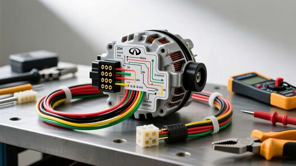
Understanding the 2015 Infiniti QX60 Alternator Wiring Diagram
The 2015 Infiniti QX60, powered by the robust 3.5L VQ35DE V6 engine, relies on a sophisticated electrical architecture to manage its continuously variable transmission (CVT), advanced climate control, and premium infotainment systems. At the heart of this system is the alternator, which does not simply output a static 14.4 volts. Instead, it operates under the control of the Intelligent Power Distribution Module (IPDM) using a smart charging strategy. Understanding the 2015 Infiniti QX60 alternator wiring diagram is critical for any technician or DIYer attempting a replacement, as a single misaligned pin or damaged sense wire will trigger a fail-safe limp mode that can mimic a dead battery or a failing transmission.
This practical how-to installation guide breaks down the OEM wiring schematics, connector pinouts, and exact torque specifications required to successfully replace the alternator on the transverse-mounted VQ35DE engine. We will also cover the common failure modes associated with the Nissan/Infiniti smart charge circuit and how to test them using a digital multimeter.
How the Infiniti Smart Charge System Works
Unlike older vehicles where the internal voltage regulator operates autonomously, the QX60 uses a 2-pin control connector to communicate with the IPDM. The IPDM monitors battery temperature, electrical load, and engine RPM to dictate the alternator field current. This reduces parasitic drag on the serpentine belt during high-load acceleration phases, improving fuel economy. However, this system is highly sensitive to voltage drops. If the IPDM loses communication with the alternator via the L (Lamp/IG) wire, or if it detects an anomaly in the S (Sense) wire, it will command the alternator to default to a base output of roughly 11.8 volts to protect the vehicle electronics. This default state illuminates the battery warning light on the combination meter and can cause the CVT to enter a protective limp mode.
OEM Alternator Connector Pinout & Wire Color Codes
The alternator features two primary electrical connections: the heavy-gauge B+ output stud and the 2-pin Sumitomo-style weather-pack control connector. Below is the definitive pinout chart based on factory service manual specifications for the 2015 model year.
| Terminal / Pin | OEM Wire Color | AWG Size | Circuit Function | Destination / Origin |
|---|---|---|---|---|
| B+ Stud | Red / Black Tracer | 4 AWG | Main DC Output | Main Fusible Link Block / Battery Positive |
| Pin 1 (L) | Blue / White Tracer | 18 AWG | Lamp / IG Signal | IPDM / Combination Meter |
| Pin 2 (S) | Red | 14 AWG | Battery Voltage Sense | Battery Positive Terminal / Fusible Link |
| Case Ground | N/A (Braided Strap) | 8 AWG | Chassis / Block Ground | Engine Block to Front Subframe |
Required Tools and Specifications
Before beginning the installation, gather the following tools and consumables to ensure a professional-grade repair:
- 10mm, 12mm, 14mm, and 17mm deep and shallow sockets
- 1/2-inch drive breaker bar and torque wrench (inch-pounds and foot-pounds)
- Serpentine belt tensioner release tool or long-handle 14mm wrench
- Digital Multimeter (DMM) for voltage drop testing
- Electrical contact cleaner and dielectric grease
- Anti-seize compound (copper or nickel grade)
Factory Torque Specifications
- B+ Terminal Nut (M8): 15 Nm (11 ft-lb)
- Alternator Mounting Bolts (M10 x 1.25): 47 Nm (35 ft-lb)
- Drive Belt Tensioner Pulley Bolt: 25 Nm (18 ft-lb)
- Battery Terminal Clamp: 5 Nm (44 in-lb)
Step-by-Step Alternator Replacement Guide
Step 1: Safety and Power Isolation
Disconnect the negative battery terminal first, followed by the positive terminal. On the QX60, it is highly recommended to perform a hard reset of the IPDM by leaving the cables disconnected for at least 15 minutes. This clears any lingering smart-charge fault codes that might prevent the new alternator from initializing correctly upon startup. Secure the cables away from the battery posts.
Step 2: Top-Down Access Preparation
While some technicians prefer removing the right-front wheel and inner fender liner to access the alternator, the top-down method is generally faster for wiring access. Remove the plastic engine cover and the air intake resonator box. Unclip the mass air flow (MAF) sensor connector and loosen the hose clamps securing the intake duct to the throttle body. Set the intake assembly aside to expose the front bank of the V6 engine where the alternator is mounted.
Step 3: Serpentine Belt Removal
Locate the automatic belt tensioner on the passenger side of the engine. Place a 14mm wrench on the tensioner pulley bolt and rotate it clockwise (towards the firewall) to relieve tension on the serpentine belt. Slip the belt off the alternator pulley and slowly release the tensioner. Inspect the belt for glazing or micro-cracks; replace if necessary.
Step 4: Disconnecting the Wiring Harness
The 2-pin connector on the Nissan/Infiniti alternator is notorious for brittle locking tabs due to prolonged heat exposure. Do not simply pull on the wires. Use a small flathead pick to gently depress the primary locking tab while simultaneously squeezing the secondary release collar on the connector. Once the control plug is free, use a 12mm deep socket to remove the M8 nut securing the 4 AWG B+ output wire. Cap the B+ wire with a clean rag or electrical tape to prevent accidental shorting if the battery was not fully isolated.
Step 5: Alternator Extraction
Remove the upper M10 mounting bolt (14mm head) and the lower M10 mounting bolt (17mm head). Note that the lower bolt may be longer than the upper bolt; keep them separated. Carefully maneuver the alternator out of its bracket. Inspect the aluminum mounting ears on the engine block for corrosion. Use a wire brush to clean the mating surfaces to ensure a perfect ground path for the alternator case.
Step 6: Installation and Wiring Reconnection
Position the new or remanufactured alternator into the bracket. Hand-thread the mounting bolts to prevent cross-threading the aluminum block. Tighten the lower bolt first, followed by the upper bolt, torquing both to 35 ft-lb. Next, reconnect the 4 AWG B+ wire to the output stud. Ensure the ring terminal is seated flat against the alternator housing and tighten the M8 nut to 11 ft-lb. Apply a small dab of dielectric grease to the 2-pin connector terminals before snapping the harness plug back into place until you hear a definitive click.
Step 7: Reassembly and Belt Routing
Reinstall the intake resonator and MAF sensor, ensuring all vacuum lines and breather hoses are securely clamped to prevent unmetered air leaks. Route the serpentine belt over the crankshaft pulley, water pump, power steering pump, and finally over the alternator pulley. Use the tensioner release tool to slip the belt onto the tensioner pulley.
Step 8: IPDM Reset and Voltage Verification
Reconnect the positive battery terminal, followed by the negative terminal. Torque the battery clamps to 44 in-lb. Start the engine and allow it to idle. Using your DMM, measure the voltage at the battery posts. You should see an initial reading of 14.2 to 14.6 volts. Turn on the headlights, rear defroster, and HVAC blower to maximum. The IPDM should detect the load and command the alternator to maintain or slightly increase voltage. If the voltage drops below 13.0 volts under load, proceed to the troubleshooting section.
Common Wiring Failure Modes & Troubleshooting
If you have installed a known-good alternator but the battery light remains illuminated or the system voltage hovers around 11.8 volts, you are likely dealing with a wiring harness fault rather than a mechanical alternator failure.
1. The S-Wire Voltage Drop Test
The 14 AWG Red sense wire provides the internal regulator with a direct reading of battery voltage. If this wire suffers from internal corrosion or a poor connection at the fusible link, the regulator will incorrectly assume the battery is fully charged and taper off output. To test this, set your DMM to DC Volts. Place the red probe on the S terminal of the alternator connector (backprobing carefully) and the black probe directly on the positive battery post. With the engine running and loaded, the voltage drop must read less than 0.2V. A reading higher than 0.3V indicates high resistance in the sense circuit requiring a wire repair or terminal replacement.
2. IPDM Communication Loss (L-Wire Fault)
If the Blue/White L-wire is severed or shorted to ground, the IPDM cannot command the alternator to increase output during heavy electrical loads. This will trigger a U-code in the IPDM and force the alternator into the 11.8V fail-safe mode. Inspect the harness routing near the front engine mount, as engine movement over time can cause the loom to chafe against the aluminum mounting bracket.
3. Poor Case Grounding
The alternator relies on its physical mounting to the engine block for its ground return path. If the block mating surface was not cleaned during Step 5, or if the main engine-to-chassis braided ground strap is corroded, the alternator will struggle to output maximum amperage. Always perform a voltage drop test across the alternator case to the negative battery terminal to verify ground integrity.
Authoritative References
For further technical data, factory service manual (FSM) schematics, and community-tested diagnostics regarding the VQ35DE platform, consult the following resources:
- NicoClub QX60 & Pathfinder Technical Forums - Comprehensive FSM wiring diagrams and IPDM reset procedures.
- SAE J1171 Standard - Specifications for marine and automotive electrical connector corrosion resistance and voltage drop tolerances.
- InfinitiHelp.com - OEM technical service bulletins (TSBs) regarding smart charge system limp modes and CVT integration.