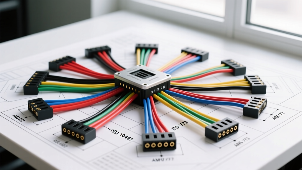
Decoding the Wiring Diagram for Car Sound System Integration
When installing, upgrading, or troubleshooting an automotive audio setup, interpreting the correct wiring diagram for car sound system integration is the difference between a flawless OEM-plus finish and a catastrophic electrical failure. Modern vehicles utilize complex multiplexed data networks, high-current power distribution modules, and impedance-sensitive speaker outputs. To navigate these systems, automotive electrical technicians rely on two primary global standards: the EIA RS-773 / CEA standard (predominant in North American aftermarket applications) and the ISO 10487 standard (the global benchmark for OEM head unit connections).
This technical specification reference provides the exact pinouts, wire color codes, AWG (American Wire Gauge) requirements, and diagnostic procedures necessary to properly execute any wiring diagram for car sound system installations. Whether you are bypassing a factory amplifier, integrating a DSP (Digital Signal Processor), or routing high-current amplifier power, adherence to these specifications ensures signal integrity and electrical safety.
EIA RS-773 Standard: North American Aftermarket Color Codes
The Consumer Technology Association (formerly the Electronic Industries Alliance, or EIA) established the RS-773 standard to unify the wire color codes for aftermarket car audio head units and wiring harness adapters. When reviewing a North American wiring diagram for car sound system harnesses, you will encounter the following standardized color matrix. Adhering to these colors and their corresponding AWG ratings prevents voltage drop and thermal failures.
| Wire Color | Function | Standard AWG | Technical Notes & Failure Modes |
|---|---|---|---|
| Yellow | 12V Constant (Memory) | 14 - 16 AWG | Supplies ECU memory and standby power. Swapping with Red causes parasitic battery draw. |
| Red | 12V Switched (Accessory) | 14 - 16 AWG | Triggers head unit power-on. Must be tied to an ignition-controlled circuit or CAN-bus interface. |
| Black | Chassis Ground | 14 - 16 AWG | Must be terminated to bare, unpainted metal. Poor grounding introduces alternator whine. |
| Orange / Orange-White | Illumination / Dimmer | 18 AWG | PWM (Pulse Width Modulated) on modern vehicles. Requires a PAC TR-4 or similar step-down module. |
| Blue / Blue-White | Power Antenna / Amp Remote | 18 AWG | Outputs +12V when the unit is on. Max current draw is typically 300mA; use a relay for multiple amps. |
| White / White-Black | Left Front Speaker (+ / -) | 16 - 18 AWG | Do not ground the black-striped wires to the chassis on BTL (Bridge-Tied Load) amplifier outputs. |
| Gray / Gray-Black | Right Front Speaker (+ / -) | 16 - 18 AWG | Phase reversal (swapping +/-) causes destructive acoustic interference at the crossover point. |
| Green / Green-Black | Left Rear Speaker (+ / -) | 16 - 18 AWG | Ensure OEM premium amp (e.g., Bose, JBL) is bypassed if using these low-level outputs. |
| Purple / Purple-Black | Right Rear Speaker (+ / -) | 16 - 18 AWG | Verify continuity to voice coils; infinite resistance indicates a severed OEM wire in the door boot. |
ISO 10487 Specification: Global OEM Head Unit Pinouts
For European, Asian, and global platforms, the ISO 10487 standard dictates the physical connector dimensions and pin assignments for automotive radios. A standard ISO wiring diagram for car sound system integration features two primary 8-pin blocks: Block A (Power and Data) and Block B (Speaker Outputs). Modern vehicles often supplement these with a Quadlock (VW/Audi/BMW) or Fakra connector, but the fundamental pinout logic traces back to ISO 10487.
Block A: Power and Control (ISO 10487-2)
- Pin 4 (Battery +): Permanent 12V supply. Typically Yellow.
- Pin 5 (Illumination): Dashboard lighting feed. Often Orange or Brown.
- Pin 6 (Mute / Tel Mute): Logic-level ground or +12V trigger to mute audio during Bluetooth/Phone calls.
- Pin 7 (Accessory +): Switched 12V ignition feed. Typically Red.
- Pin 8 (Ground): Main power ground. Typically Brown or Black.
Note: Pins 1, 2, and 3 are reserved for manufacturer-specific CAN-bus, steering wheel controls, or speed-dependent volume control (SDVC) signals.
Block B: Speaker Outputs (ISO 10487-2)
- Pin 1 & 2: Right Rear (+ / -)
- Pin 3 & 4: Right Front (+ / -)
- Pin 5 & 6: Left Front (+ / -)
- Pin 7 & 8: Left Rear (+ / -)
For detailed international standard documentation, refer to the ISO 10487 standard catalog.
High-Current Amplifier & DSP Wiring Specifications
A standard head unit wiring diagram is only half the battle. High-performance sound systems require dedicated power distribution. According to SAE J1128 guidelines for automotive wire ampacity, selecting the correct AWG based on total current draw and cable length is critical to preventing thermal events and voltage sag.
| Total System Wattage (RMS) | Max Current Draw (@ 12.5V) | Recommended Power/Ground AWG | Fusing Requirement |
|---|---|---|---|
| Up to 250W | ~25 Amps | 10 AWG OFC | 30A ATO/ATC Blade |
| 250W - 600W | ~50 Amps | 8 AWG OFC | 60A ANL / Maxi Fuse |
| 600W - 1200W | ~100 Amps | 4 AWG OFC | 120A ANL / Class-T |
| 1200W - 2500W+ | 200+ Amps | 1/0 AWG OFC | 250A+ ANL / Class-T |
Installation Best Practices: Always use Oxygen-Free Copper (OFC) rather than Copper-Clad Aluminum (CCA). CCA wire has higher resistance and is prone to galvanic corrosion when crimped with standard copper terminals. All main power connections must be terminated with adhesive-lined heat shrink ring terminals and torqued to manufacturer specifications (typically 10-12 Nm for M6 battery terminal bolts).
CAN-Bus and Data Network Integration
In late-model vehicles, the traditional "switched 12V" accessory wire no longer exists. The vehicle's Body Control Module (BCM) manages power states via a CAN-bus network. When your wiring diagram for car sound system integration involves a CAN-bus interface (such as an Axxess ASWC-1 or iDatalink Maestro), you must tap into the high-speed or medium-speed CAN network.
- CAN-High (CAN-H): Typically operates at a dominant voltage of 3.5V and a recessive voltage of 2.5V.
- CAN-Low (CAN-L): Typically operates at a dominant voltage of 1.5V and a recessive voltage of 2.5V.
- Connector Type: OEM connections frequently use Molex MX150 or TE Connectivity AMP Timer sealed connectors. Never use Scotch-lok T-taps on CAN-bus wires; the added capacitance and risk of strand severing will throw U-codes (e.g., U0155 - Lost Communication with Instrument Panel Cluster).
- Termination: The CAN-bus relies on two 120-ohm termination resistors at opposite ends of the network. When integrating DSPs that read CAN data, ensure the interface module is high-impedance so as not to collapse the network voltage.
Diagnostic Troubleshooting: Ground Loops and Parasitic Draws
Even with a perfect wiring diagram for car sound system layouts, real-world variables introduce electrical anomalies. Use the following diagnostic decision tree to resolve common integration failures:
1. Alternator Whine (Ground Loop Isolation)
Symptom: A high-pitched whine that modulates with engine RPM.
Cause: A difference in electrical potential between the head unit ground and the amplifier ground, causing current to flow through the shield of the RCA interconnects.
Fix: 1. Set a Digital Multimeter (DMM) to AC Millivolts. 2. Place the positive probe on the RCA shield of the amplifier and the negative probe on the head unit chassis. 3. If a voltage difference > 5mV is detected, re-route the amplifier ground to the exact same chassis grounding point as the head unit, or install a 1:1 ground loop isolator on the RCA lines.
2. Parasitic Battery Drain
Symptom: Dead battery after the vehicle sits for 48 hours.
Cause: The head unit's Yellow (Constant) and Red (Switched) wires are reversed, or an amplifier remote turn-on wire is back-feeding a BCM circuit.
Fix: 1. Disconnect the negative battery terminal. 2. Connect a DMM set to DC Amps (10A scale) in series between the negative post and the disconnected cable. 3. Wait 15 minutes for all vehicle modules to enter "sleep" mode. 4. If the draw exceeds 50mA (0.05A), pull the main audio system fuse. If the drop ceases, isolate the amplifier remote turn-on circuit and verify it is not back-feeding the CAN-bus or BCM via a faulty relay.
3. Speaker Pop / Turn-On Thump
Symptom: Loud mechanical "pop" from subwoofers when the ignition is turned on or off.
Cause: The amplifier is turning on and charging its internal capacitors before the head unit's DSP/mute circuit has fully stabilized.
Fix: Install a 1-second to 3-second soft-start delay relay on the Blue/White remote turn-on wire between the head unit and the amplifier. This ensures the audio signal source is fully booted and muted before the amplifier's output stage is energized.
For comprehensive vehicle-specific installation guides, wiring harness pinouts, and firmware updates for data interfaces, consult the Metra Electronics Technical Support Database or the manufacturer's official service manuals.