The Foundation of Savana Electrical Diagnostics
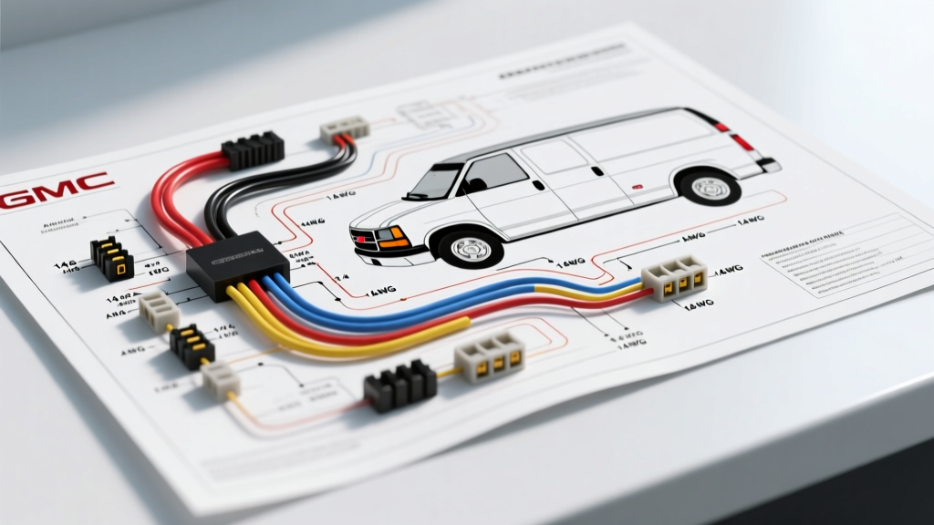
The GMC Savana and its Chevrolet Express sibling represent some of the most versatile and enduring platforms on the road. Whether you are diagnosing a faulty headlight circuit, planning a complex camper van conversion, or integrating aftermarket ambulance equipment, mastering the GMC Savana wiring diagram is your first critical step. Unlike passenger cars, the Savana’s GMT610 platform is designed with heavy-duty upfitter integration in mind, meaning its electrical architecture is robust, modular, and heavily reliant on dedicated bussed electrical centers.
For beginners, looking at a factory service manual schematic can feel like reading an alien language. However, General Motors uses a highly standardized, logical system for their wiring schematics. By understanding the core symbols, wire color codes, and connector families used in the Savana, you can confidently trace circuits from the battery to the ground node without guessing. This guide breaks down the fundamentals of GM’s electrical documentation, providing you with the actionable knowledge needed to troubleshoot and modify your van safely.
Decoding Standard GM Schematic Symbols and Grids
Official GM service manuals, typically published by Helm Incorporated, organize wiring diagrams using a coordinate grid system. The edges of the diagram are labeled with letters (A, B, C) across the top and numbers (1, 2, 3) down the sides. When a wire crosses from one page to another, the diagram will display a grid coordinate (e.g., 'B4') inside a small box, telling you exactly where to find the continuation of that circuit on the next page.
Understanding the core symbols is equally important:
- Splice Packs (SP): Represented by a solid black circle with multiple lines radiating outward. In the Savana, you will frequently see SP100 or SP200, which are physical brass crimp sleeves used to join multiple ground or power wires together without daisy-chaining them, ensuring equal voltage distribution.
- Ground Nodes (G): Denoted by a standard ground symbol with a specific alphanumeric code (e.g., G100, G200). These correspond to physical bolt locations on the chassis or engine block.
- Connectors (C): Labeled with a 'C' followed by a number (e.g., C101). The diagram will show the connector cavity numbers, allowing you to identify exactly which pin corresponds to which wire.
- Switches and Relays: Shown in their 'at-rest' or 'de-energized' state. A relay coil is depicted as a rectangle, while the internal switch contacts are shown open or closed depending on their default resting position.
GM Wire Color Codes and AWG Specifications
General Motors adheres to strict color-coding conventions to help technicians quickly identify a wire's purpose. Furthermore, the insulation and gauge of the wire are dictated by the SAE J1128 Low Tension Cable Standard. In the engine bay, the Savana utilizes GXL (cross-linked polyethylene) wire for its superior heat and chemical resistance. Inside the cabin, TXL (thin-wall cross-linked) wire is used to reduce harness weight and bulk.
Below is a reference table for the most common wire colors and American Wire Gauge (AWG) sizes you will encounter when reading a GMC Savana wiring diagram.
| Color Code | Base Color | Typical Application | Common AWG Range |
|---|---|---|---|
| BK | Black | Main Ground / Chassis Return | 18 - 4 AWG |
| OG | Orange | Constant Battery Positive (B+) | 14 - 8 AWG |
| RD | Red | Switched Battery / Ignition Feed | 18 - 12 AWG |
| YE | Yellow | PCM/ECM Sensor Signals & Data | 22 - 18 AWG |
| GY | Gray | Low Reference / Sensor Return | 22 - 18 AWG |
| DK GRN | Dark Green | Right Turn / Stop Lamp Circuit | 16 - 14 AWG |
| LT BLU | Light Blue | Left Turn / High Beam Circuits | 16 - 14 AWG |
Note: A wire with a tracer (stripe) will be listed with the base color first, followed by the stripe color (e.g., BK/WH is Black with a White stripe).
Navigating GM Metri-Pack and Weather-Pack Connectors
The Savana relies heavily on the Delphi (now Aptiv) Metri-Pack and Weather-Pack connector families. Understanding these physical connectors is crucial when a wiring diagram tells you to test 'Connector C105, Pin B2'.
- Metri-Pack 150 Series: These are the small, tightly sealed connectors used for low-current sensors (e.g., MAP sensor, IAT sensor, oxygen sensors). The terminals are rated for up to 15 amps but typically carry milliamp-level signals. They feature a secondary lock (TPA) to prevent terminal back-out.
- Metri-Pack 280 Series: Used for medium to high-current applications like fuel injectors, ignition coils, and main ECM power feeds. The '280' refers to the width of the terminal blade (2.8mm).
- Weather-Pack: Recognizable by their bulky, rounded housings and large silicone weather seals. These are primarily used for exterior lighting, trailer tow packages, and underbody connections where extreme moisture exposure is expected.
Step-by-Step: Tracing the Headlight Circuit
To put your knowledge of the GMC Savana wiring diagram into practice, let us trace a standard low-beam headlight circuit from the power source to the ground.
- Power Source: The circuit begins at the battery and travels via a heavy-gauge (typically 8 AWG Red) cable to the Underhood Bussed Electrical Center (UBEC).
- UBEC Fuse and Relay: Inside the UBEC, the power passes through the HEADLAMP fuse. When the driver activates the headlight switch on the steering column, a low-current signal energizes the Headlamp Relay coil. The relay closes its internal contacts, allowing high-current battery power to flow to the left and right headlight fuses.
- Cabin Routing: From the UBEC, the power travels through the firewall bulkhead connector (often C100 or C101) into the cabin, routing through the Instrument Panel (IP) harness to the front lighting harness.
- The Load (Bulb): The 14 AWG Light Blue (LT BLU) or Yellow (YE) wire delivers 12V to the headlamp bulb socket.
- Ground Return: The current passes through the bulb filament and exits via a 14 AWG Black (BK) wire. This wire travels a short distance to Ground Node G100 (Left Front Fender) or G200 (Right Front Fender), where it bolts to the chassis, completing the circuit back to the battery's negative terminal.
Common GMC Savana Wiring Failure Points
When using a wiring diagram to diagnose a fault, it helps to know where the GMT610 platform is most vulnerable. According to the GM Upfitter Integration Guides and field service bulletins, Savana vans suffer from a few recurring electrical gremlins:
- Ground Node Corrosion (G100 / G200): The front fender grounds are exposed to road spray and salt. A corroded G100 will cause dim headlights, erratic PCM behavior, and alternator charging issues. Always check the physical ground bolt before replacing expensive control modules.
- Firewall Bulkhead Water Ingress: The large pass-through connectors on the firewall can suffer from degraded silicone mat seals. Water wicks into the connector cavities, causing green verdigris corrosion on the Metri-Pack terminals, leading to high-resistance CAN bus faults.
- Parking Brake Pedal Chafing: The main IP harness routes dangerously close to the parking brake pedal assembly in older Savana models. Repeated use can wear through the harness loom and tape, shorting the 12V Orange (OG) battery feed against the metal pedal bracket, frequently blowing the main IGN fuse.
Pro-Tips for Multimeter Back-Probing
When your Savana wiring diagram directs you to test a specific pin at the ECM or a sensor connector, never pierce the wire insulation with a multimeter probe. Piercing GXL/TXL insulation creates a microscopic hole that traps moisture, leading to copper oxidation and eventual wire failure. Instead, use dedicated T-pins or specialized back-probing picks to slide past the rubber weather seal and make contact with the terminal from the rear of the connector. This ensures you are reading the exact voltage present at the component while maintaining the integrity of the harness seal.