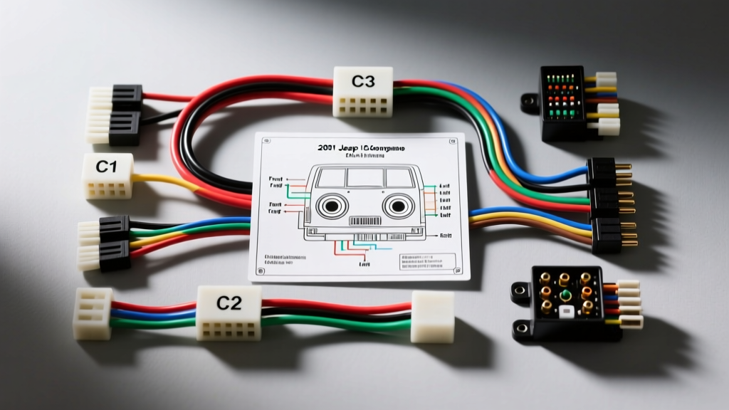
Introduction to the 2001 XJ Platform Audio Harness
The 2001 model year marks the final production run of the legendary Jeep Cherokee XJ platform. When upgrading the audio system in a 2001 XJ, understanding the factory stereo wiring diagram is critical. Unlike modern vehicles that rely heavily on CAN-bus systems for basic audio routing, the 2001 Cherokee utilizes a traditional analog speaker-level output system paired with a Chrysler-specific Programmable Communications Interface (PCI) bus for diagnostic and steering wheel control data. Misinterpreting the 2001 Jeep Cherokee stereo wiring diagram can lead to blown head unit fuses, erratic instrument cluster behavior, or damaged Body Control Modules (BCM).
This technical specification reference provides the exact OEM wire color codes, connector pinouts, AWG ratings, and troubleshooting data required to safely integrate an aftermarket head unit, bypass the factory Infinity amplifier, or diagnose existing audio faults.
OEM Radio Connector Architecture
The 2001 Jeep Cherokee factory radio harness consists of three primary connectors, commonly bundled together in a single grey plastic housing but electrically isolated. When purchasing an aftermarket wiring harness adapter (such as the Metra 70-1004 or Scosche CR02B), you are essentially mating with these three distinct circuits.
- C1 (Power and Data): A 7-pin connector responsible for constant power, switched ignition power, chassis ground, illumination, and the PCI data bus.
- C2 (Front Speakers): An 8-pin connector housing the front left and front right speaker outputs. Only 4 of the 8 cavities are populated.
- C3 (Rear Speakers): An 8-pin connector housing the rear left and rear right speaker outputs. Only 4 of the 8 cavities are populated.
The terminals used in these connectors are Delphi Packard GT 150 series. If you need to extract a pin for repair or custom harness fabrication, you must use a GT 150 terminal extraction tool to avoid destroying the delicate locking tangs, which become highly brittle after two decades of heat cycling inside the dashboard.
C1 Power and Data Pinout Specifications
The C1 connector is the lifeline of the head unit. Pay special attention to Pin 6. The PCI bus wire (Violet/Yellow) is a high-speed data line shared with the BCM and the overhead console. Do not tap into, ground, or apply 12V to this wire. Back-feeding voltage into the PCI bus from an aftermarket stereo's illumination or dimmer circuit will cause the vehicle's gauges to sweep erratically and can permanently corrupt the BCM.
| Pin | Wire Color | Function | AWG | Notes |
|---|---|---|---|---|
| 1 | Pink | Constant 12V+ (Battery) | 16 AWG | Supplies memory for radio presets and clock. |
| 2 | White/Red | Switched 12V+ (Ignition) | 16 AWG | Turns head unit on/off with the ignition key. |
| 3 | Black | Chassis Ground | 16 AWG | Must have less than 0.1 ohms of resistance to battery negative. |
| 4 | Orange | Illumination / Dimmer | 18 AWG | Varies from 12V (lights off) to 0V (lights on/dimmed). |
| 5 | - | Empty | - | Reserved cavity. |
| 6 | Violet/Yellow | PCI Data Bus | 18 AWG | CRITICAL: Cap off and isolate. Do not connect to aftermarket harness. |
| 7 | - | Empty / Mute | - | Used only on specific fleet/telephone-equipped models. |
C2 and C3 Speaker Routing & Color Codes
The XJ platform routes speaker-level audio directly from the head unit to the door panels and rear quarter panels. The OEM speaker wire is 18 AWG, which is sufficient for the factory 15W RMS head unit but will introduce voltage drop and thermal compression if you install an aftermarket unit pushing 50W+ RMS per channel.
C2 Connector: Front Speakers
| Pin | Wire Color | Function | Polarity |
|---|---|---|---|
| 1 | Dark Green | Front Left Speaker | Positive (+) |
| 2 | Brown/Red | Front Left Speaker | Negative (-) |
| 3 | Violet | Front Right Speaker | Positive (+) |
| 4 | Dark Blue/Red | Front Right Speaker | Negative (-) |
C3 Connector: Rear Speakers
| Pin | Wire Color | Function | Polarity |
|---|---|---|---|
| 1 | Brown/Yellow | Rear Left Speaker | Positive (+) |
| 2 | Brown/Light Blue | Rear Left Speaker | Negative (-) |
| 3 | Dark Blue/Orange | Rear Right Speaker | Positive (+) |
| 4 | Dark Blue/White | Rear Right Speaker | Negative (-) |
Infinity Amplifier Bypass Procedures
Some 2001 Jeep Cherokees were equipped with the optional Chrysler Infinity premium audio system. If your XJ has the Infinity badge on the head unit or door grilles, the factory radio outputs a line-level signal to an external amplifier located in the rear right quarter panel behind the interior trim. The amplifier then powers the speakers.
When installing an aftermarket head unit with built-in amplification (typically 4x50W), you cannot simply plug the standard adapter harness into the factory Infinity wiring. The aftermarket head unit's amplified output will clash with the factory amp's input stage, resulting in severe distortion or blown output ICs.
Expert Bypass Strategy: Rather than attempting to repurpose the thin, shielded line-level wiring running from the dash to the rear quarter panel, the most reliable method is to run new 16 AWG speaker wire from the aftermarket head unit directly to the rear speakers. You will use the C1 power adapter, but you will bypass the C3 connector entirely, routing your new 16 AWG wire through the factory rubber door boots and under the carpet to the rear speaker locations. For a comprehensive visual guide on harness adapters and Infinity bypass kits, consult the Crutchfield Vehicle Fitment Database.
Wire Gauge, AWG Ratings, and Voltage Drop
According to the SAE J1128 Low Tension Primary Cable Standard, the OEM 18 AWG wire used in the XJ speaker circuits has a maximum continuous current rating of approximately 16 Amps in a chassis wiring environment. However, audio signals are dynamic. Pushing 50W RMS into a 4-ohm speaker requires roughly 3.5 Amps of continuous current, but transient peaks can demand much more.
The run from the dashboard to the rear speakers in a 4-door Cherokee is approximately 12 to 14 feet. Using 18 AWG copper wire over a 14-foot run at 5 Amps will result in a voltage drop of roughly 0.35V. While this seems negligible, it reduces the damping factor of the amplifier, leading to muddy, uncontrolled bass response in the rear doors. Upgrading to 16 AWG (or 14 AWG for subwoofer runs) is highly recommended for any aftermarket installation exceeding 25W RMS per channel.
Common XJ Audio Wiring Failure Modes & Troubleshooting
When diagnosing a dead stereo or intermittent audio loss in a 2001 Cherokee, verify the following common failure points before replacing the head unit:
- Ground G200 Corrosion: The primary ground for the radio harness is Ground G200, located behind the left kick panel near the hood release. Moisture intrusion from the cowl drains often causes this ground point to corrode, resulting in a head unit that turns on but produces no audio, or audio that cuts out when hitting bumps. Clean the ring terminal and the chassis contact point with a wire brush and apply dielectric grease.
- Memory Loss (Clock Resetting): If the radio loses its presets and clock every time the key is turned off, the Pink (Constant 12V) and White/Red (Switched 12V) wires have likely been swapped at the aftermarket harness adapter. Verify with a multimeter at the vehicle-side C1 connector before applying power.
- Blown Fuse 12: The radio's constant power circuit is protected by Fuse 12 (10A) located in the Junction Block behind the glove box. If this fuse blows immediately upon insertion, inspect the Pink wire where it passes through the firewall or under the dash for chafing against the steering column bracket.
- Brittle Insulation: The 2001 XJ is over two decades old. The OEM PVC wire insulation, particularly near the back of the radio where heat builds up, becomes glass-like and shatters when bent. Use heat shrink tubing and adhesive-lined marine shrink to repair any cracked insulation near the C1/C2/C3 connectors to prevent short circuits against the metal radio sleeve.
Authoritative References
- Haynes Jeep Cherokee Repair Manual - Comprehensive chassis and electrical schematics for the 1984-2001 XJ platform.
- SAE J1128 Low Tension Primary Cable Standard - Engineering specifications for automotive wire gauge, thermal ratings, and insulation requirements.
- Crutchfield Vehicle Fitment Database - Verified harness adapter compatibility and Infinity amplifier bypass configurations for the 2001 XJ.