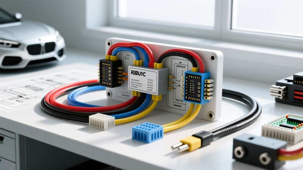
Introduction to the RIBU1C in Advanced Automotive Applications
When building custom automotive, marine, or off-road electrical systems, standard Bosch-style 40A relays often fall short in harsh environments. The Functional Devices, Inc. (FDI) RIBU1C encapsulated relay has become a staple among advanced automotive electricians and marine fabricators. Unlike open-frame relays, the RIBU1C is fully potted in a polyurethane resin, providing exceptional resistance to moisture, vibration, and corrosive under-hood chemicals. This deep dive explores the RIBU1C wiring diagram PDF specifications, translating industrial control schematics into actionable, vehicle-specific integration guides for high-draw auxiliary accessories.
Whether you are designing an ECU-triggered dual fuel pump setup, wiring a marine winch solenoid, or integrating low-side switched off-road LED light bars, understanding the exact pinout, wire color codes, and AWG limitations of the RIBU1C is critical. This guide bypasses generic advice and provides the exact technical parameters required for professional-grade vehicle wiring.
RIBU1C Pinout and Wire Color Code Reference
The RIBU1C is a Single Pole Double Throw (SPDT) relay with a versatile 10-30V AC/DC coil. This wide coil voltage range means the same relay can be deployed in 12V passenger vehicles, 24V heavy-duty trucks, and marine systems without swapping components. The pigtails are pre-stripped and tinned, typically measuring 6 inches in length.
| Wire Color | Function | Internal Connection | AWG Size | Max Continuous Load |
|---|---|---|---|---|
| Yellow | Coil Positive (+) | Internal Bridge Rectifier | 18 AWG | N/A (Control Circuit) |
| Orange | Coil Negative (-) | Internal Bridge Rectifier | 18 AWG | N/A (Control Circuit) |
| Red | Common (COM) | Switched Contact Armature | 14 AWG | 20A @ 30VDC |
| Black | Normally Open (NO) | NO Contact Point | 14 AWG | 20A @ 30VDC |
| Blue | Normally Closed (NC) | NC Contact Point | 14 AWG | 20A @ 30VDC |
Note: While the RIBU1C contacts are rated for 20A, automotive best practices dictate that continuous inductive loads (like fuel pumps or winch solenoids) should not exceed 80% of the relay's maximum rating (16A) to prevent contact welding and voltage drop over time.
Scenario A: ECU-Triggered Auxiliary Fuel Pump Integration
In high-horsepower applications, an ECU (such as a Holley Terminator X or MoTeC M150) often uses a low-current, low-side driver to trigger a secondary fuel pump. The RIBU1C is ideal for this due to its low coil current draw (approximately 45mA at 12VDC), which safely sits well within the 1A-2A limit of most aftermarket ECU programmable outputs.
Wiring Execution Steps
- Control Circuit (Coil): Connect the Yellow wire to a switched 12V ignition source (protected by a 2A mini-ATM fuse). Connect the Orange wire directly to the ECU's low-side driver output pin.
- Load Circuit (Contacts): Run 12 AWG primary wire from the battery positive terminal (via a 30A circuit breaker) to the relay's Red (COM) wire. Use a step-down crimp sleeve or a sealed Weather Pack connector to adapt the 12 AWG main harness to the 14 AWG RIBU1C pigtail.
- Output to Pump: Connect the Black (NO) wire to the positive terminal of the auxiliary fuel pump. Ground the fuel pump to the chassis using a dedicated 10 AWG ground strap, ensuring bare metal contact and applying dielectric grease to the terminal.
Flyback Diode Considerations
While the RIBU1C contains an internal bridge rectifier to accommodate AC/DC coil inputs, sensitive ECU drivers can still be vulnerable to inductive kickback (voltage spikes) when the coil's magnetic field collapses. According to SAE J1113 Electromagnetic Compatibility standards, it is highly recommended to solder a 1N4004 flyback diode across the Yellow and Orange wires, with the diode's cathode (stripe) facing the Yellow (positive) wire. This clamps the voltage spike and protects the ECU's internal transistor.
Scenario B: High-Current Off-Road Lighting via Low-Side Switch
Many modern off-road vehicles utilize CAN-bus systems or low-side switches on the steering column that cannot handle the raw current of multiple LED light bars. The RIBU1C's encapsulated housing makes it perfect for mounting in the engine bay or on the chassis near the winch fairlead, where water and mud ingress would destroy a standard relay.
- Trigger: The factory auxiliary switch provides a ground path when activated. Wire the Orange coil wire to the factory switch ground trigger. Wire the Yellow coil wire to a fused 12V ignition source.
- Load: Wire the battery to the Red (COM) wire via a 15A fuse. Wire the Black (NO) wire to the Deutsch DT connector positive pin feeding the LED light bar relay harness.
- Sealing: Because the RIBU1C pigtails are solid wire or stranded tinned copper, any splices made in the engine bay must be sealed using 3M dual-wall, adhesive-lined heat shrink (3/16 inch diameter). This prevents capillary action from drawing moisture into the relay housing.
Interpreting the RIBU1C Wiring Diagram PDF
When sourcing the official Functional Devices RIBU1C datasheet and wiring diagram PDF, automotive electricians often notice the schematic uses industrial automation symbols rather than standard automotive DIN/ISO relay symbols. Here is how to translate the PDF schematic to automotive terms:
Schematic Translation Guide
- Coil Symbol (Rectangle): In the PDF, the coil is represented by a standard IEC rectangle. In automotive terms, this is your trigger circuit (terminals 85 and 86 on a Bosch relay).
- COM / NO / NC Nodes: The PDF shows a single switch blade (COM/Red) resting against the NC/Blue contact. When 10-30V is applied to the coil, the blade moves to the NO/Black contact. This maps exactly to terminals 30 (COM), 87a (NC), and 87 (NO) on a standard 5-pin automotive relay.
- Internal Rectifier Bridge: The PDF schematic often omits the internal diode bridge for simplicity. Remember that because of this bridge, the Yellow and Orange wires are non-polarized for DC applications—you can wire them backward and the relay will still engage. However, maintaining Yellow-to-Positive and Orange-to-Negative is best practice for troubleshooting consistency.
Advanced Troubleshooting and Failure Modes
Even fully encapsulated relays can fail if subjected to automotive electrical abuse. If your accessory is not engaging, use a digital multimeter (DMM) to diagnose the following specific RIBU1C failure modes:
1. Voltage Drop Across the Contacts
With the relay energized and the accessory running, place your DMM probes on the Red (COM) wire and the Black (NO) wire, as close to the relay housing as possible. A healthy RIBU1C should show a voltage drop of less than 0.1V (100mV). If you read 0.5V or higher, the internal contacts are pitted or carbon-fouled from switching high inductive loads without a snubber circuit. The relay must be replaced.
2. Coil Resistance Testing
Disconnect the relay from all vehicle power. Set your DMM to measure Ohms (Ω). Place the probes on the Yellow and Orange wires. A healthy 10-30V AC/DC coil will typically read between 350Ω and 450Ω. If you read an open circuit (OL), the internal coil wire has fractured, often due to excessive vibration or thermal cycling. If you read near 0Ω, the internal bridge rectifier has shorted.
3. Thermal Runaway on 14 AWG Pigtails
If the RIBU1C is used to switch a 20A continuous load, the 14 AWG pigtails can become warm. According to standard AWG ampacity charts, 14 AWG wire is rated for 15A in automotive chassis wiring (which accounts for high ambient under-hood temperatures). If your accessory draws 18A-20A continuously, you must upgrade the wiring immediately after the RIBU1C pigtails to 12 AWG or 10 AWG, and consider mounting the relay in a high-airflow area or using a heatsink compound on the mounting bracket to dissipate internal contact heat.
Final Integration Best Practices
When mounting the RIBU1C, utilize the integrated mounting flange. Use stainless steel hardware (#8 or #10 screws) with a star washer to ensure a solid mechanical connection, but do not over-torque. The polyurethane potting compound is tough, but cracking the housing via excessive torque on the mounting tab will compromise the IP67-level moisture seal. Apply a dab of silicone RTV over the screw head to prevent galvanic corrosion between the steel screw and the aluminum or steel mounting surface.
By treating the RIBU1C not just as an industrial part, but as a high-reliability automotive component, you can build auxiliary wiring harnesses that survive the harshest off-road, marine, and racing environments. Always reference the manufacturer's latest RIBU1C wiring diagram PDF for batch-specific revisions, and adhere strictly to SAE J1113 guidelines for transient suppression.