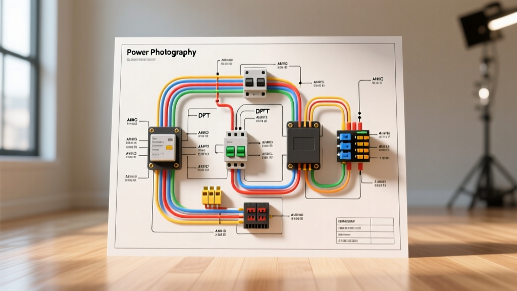
Architecture of the Dual-Reversing Power Window Circuit
When interpreting a complex wiring diagram for power windows, technicians must recognize that the fundamental actuation relies on a permanent magnet DC motor. Unlike stepper motors or multi-phase AC motors found in HVAC systems, a standard automotive window motor features only two terminals. Directional control is achieved exclusively through polarity reversal. To facilitate this, the master switch assembly utilizes a Double-Pole, Double-Throw (DPDT) switching matrix. This matrix acts as a manual H-bridge, crossing the battery feed and ground paths to reverse the magnetic field within the motor armature.
In legacy and heavy-duty platforms, the DPDT switch handles the full stall current of the motor. However, modern architectures have largely migrated to multiplexed door modules. Understanding the transition from high-current discrete wiring to low-current serial communication is critical for accurate diagnostics. Below, we deconstruct the circuit architecture, wire gauge specifications, and pinout configurations necessary for advanced electrical troubleshooting.
Decoding the GMT800 Platform DPDT Pinout
The GM GMT800 platform (Silverado/Sierra 1999-2006) represents the pinnacle of the discrete high-current DPDT window architecture. The master switch does not rely on a Body Control Module (BCM) for basic up/down actuation; instead, it routes high-amperage current directly through the switch contacts. The OEM wiring diagram for power windows on this platform illustrates a 30-ampere circuit breaker located in the instrument panel fuse block, feeding the master switch via a heavy-gauge orange wire.
Master Switch Connector Cavity Reference (Metri-Pack 280)
| Cavity | Wire Color | AWG | Circuit Function | Destination / Splice Pack |
|---|---|---|---|---|
| A (Pin 1) | Orange (ORN) | 12 | Battery Feed (CB 30A) | Instrument Panel Fuse Block |
| B (Pin 2) | Black (BLK) | 12 | Primary Ground | SP205 (Left Kick Panel) |
| C (Pin 3) | Dark Blue (DK BLU) | 14 | Driver Motor Feed A | Driver Door Motor Terminal 1 |
| D (Pin 4) | Brown (BRN) | 14 | Driver Motor Feed B | Driver Door Motor Terminal 2 |
| E (Pin 5) | Light Green (LT GRN) | 18 | Passenger Lockout Logic | Passenger Door Switch Assembly |
| F (Pin 6) | Yellow (YEL) | 18 | Illumination Feed | Instrument Panel Dimmer Switch |
According to SAE J1128 Low Tension Primary Cable standards, the 12 AWG TXL (Thermoplastic Cross-Linked) wire used in Cavity A is rated for continuous operation at 125°C. This is mandatory because a bound-up window regulator can cause the DC motor to enter a locked-rotor stall condition, drawing upwards of 22-25 amperes before the thermal breaker trips or the 30A fuse clears. Using undersized wire or failing to secure the ground at SP205 will result in severe voltage drop, mimicking a failing motor.
Modern Multiplexing: LIN Bus and Anti-Pinch Logic
As vehicles evolved, routing 12 AWG high-current wires through the door jam boot (the flexible rubber conduit between the A-pillar and the door shell) became problematic due to weight, cost, and wire fatigue failures. Modern platforms, such as the Ford Global C1 and GM Epsilon II, utilize a Local Interconnect Network (LIN) bus. In this architecture, the master switch is merely a low-current input device. It sends serial data to the Driver Door Module (DDM), which then commands the Passenger Door Module (PDM) via the LIN bus.
Express-Up/Down and Hall-Effect Sensor Integration
One-touch express functionality requires the module to know the exact position of the glass and the direction of travel. This is achieved by embedding a dual-channel Hall-effect sensor within the motor housing. As the motor armature rotates, a multi-pole magnetic ring passes over the Hall-effect IC, generating a pulse train. By analyzing the phase shift between Channel A and Channel B (typically 90 degrees out of phase), the door module determines both speed and direction. If the module detects a sudden decrease in pulse frequency while the duty cycle remains high, it registers an obstruction and triggers the anti-pinch reversal protocol.
| Parameter | Specification | Diagnostic Notes |
|---|---|---|
| LIN Bus Voltage (Recessive) | 12.0V (Battery Voltage) | Pulled high by master node resistor |
| LIN Bus Voltage (Dominant) | 1.0V - 1.5V | Pulled low by slave node transistor |
| Baud Rate | 19.2 kbps | Requires oscilloscope, not standard DMM |
| Hall Sensor Reference | 5.0V DC | Supplied by Door Module, highly sensitive to ground offsets |
| Hall Sensor Signal | 0-5V Square Wave | Typically 30-50 pulses per full glass travel |
For in-depth module-to-module communication schematics, technicians frequently consult the Ford EVTM Wiring Manuals, which provide exhaustive node-to-node LIN bus routing diagrams and splice pack locations that are invisible to standard OBD2 scan tools.
Advanced Diagnostic Procedures & Voltage Drop Analysis
When a customer complains of slow window operation, the amateur technician replaces the motor. The master technician performs a dynamic voltage drop test across the entire DPDT matrix. A healthy switch contact and wiring harness should exhibit no more than 0.15V of drop on the power feed side and 0.10V on the ground side under full motor load.
Diagnostic Decision Tree: Sluggish or Inoperative Windows
- Symptom: Motor hums audibly, but glass stalls halfway up.
- Step 1: Measure voltage directly at the motor terminals during actuation. If voltage drops below 10.5V, proceed to Step 2. If voltage is >11.5V, the fault is mechanical (regulator bind, dry run channels).
- Step 2: Perform voltage drop test across the master switch DPDT contacts. A reading >0.3V indicates carbon tracking and pitting on the internal copper wipers. Replace the master switch assembly.
- Step 3: If switch drop is nominal, inspect the door jamb boot for broken 12 AWG wires. The constant flexing causes copper strand fatigue and localized high resistance.
- Symptom: Express-down function inoperative, but manual hold works.
- Step 1: Connect an oscilloscope to the Hall-effect signal wire at the door module connector.
- Step 2: Command the window down. Verify a clean 0-5V square wave. If the waveform is erratic or missing entirely, the internal motor magnet ring has degraded or the sensor air gap has widened due to thermal expansion. Replace the motor/sensor assembly.
- Symptom: Passenger window inoperative from both master and passenger switches.
- Step 1: Check LIN bus integrity. A short-to-ground on the single-wire LIN bus will pull the entire network down to 0V, disabling all multiplexed passenger commands.
- Step 2: Isolate the PDM (Passenger Door Module) by disconnecting it. If the LIN bus voltage returns to 12V at the DDM, the PDM has suffered an internal transceiver failure.
Connector and Terminal Service Protocols
When repairing the high-current feeds identified in the wiring diagram for power windows, soldering is strictly prohibited in high-flex zones like the door jamb. Solder creates a rigid point that will quickly fatigue and snap under the repeated stress of door opening and closing. Instead, technicians must use OEM-spec crimp barrels and heat-shrink tubing. For the Metri-Pack 280 series terminals commonly used in these circuits, the Aptiv Metri-Pack 280 Series documentation mandates the use of a controlled-cycle crimp tool to ensure the terminal tangs properly engage the connector housing lock. A poorly seated terminal will back out over time, leading to an open circuit that can strand the glass in the down position.
Summary of System Evolution
Mastering automotive glass actuation requires a dual understanding of legacy high-current physics and modern serial data networks. Whether you are tracing a 12 AWG battery feed through a GMT800 DPDT switch or analyzing a 19.2 kbps LIN bus waveform on a late-model global platform, the foundational rules of electrical diagnostics remain unchanged: verify the power, validate the ground, and isolate the control logic. By adhering to SAE wire standards and utilizing dynamic voltage drop testing, technicians can accurately pinpoint failures without resorting to unnecessary parts replacement.