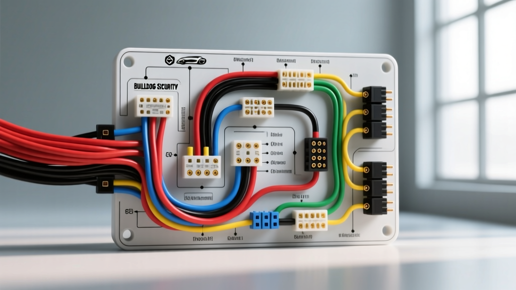
Introduction to Bulldog Security Harness Architecture
Integrating an aftermarket security and remote start module requires a precise understanding of the vehicle's electrical topology. The Bulldog security car wiring diagram serves as the foundational blueprint for installers and automotive electricians. Unlike basic alarm systems, modern Bulldog modules interface directly with multiplexed CAN bus networks, high-current ignition circuits, and OEM immobilizer bypass protocols. This technical specification reference breaks down the primary harness pinouts, wire gauge requirements, and external relay configurations necessary for a flawless installation.
When referencing any Bulldog security car wiring diagram, it is critical to verify the specific module generation (e.g., 530T vs. 535T series), as firmware updates often reassign data bus communication pins. Proper integration relies on adhering to SAE J1128 standards for low-tension primary cable selection, ensuring that aftermarket wiring matches or exceeds the OEM copper stranding and insulation thermal ratings.
Main Power, Ground, and Ignition Harness Specifications
The primary 12-pin Molex Mini-Fit Jr. connector handles the high-current distribution and ignition logic. Voltage drop across these circuits is the leading cause of remote start failures and parasitic battery drain. All primary power and ground connections must be terminated using closed-end barrel crimps with adhesive-lined heat shrink, avoiding T-taps which compromise the OEM wire strand integrity.
Primary 12-Pin Harness Pinout Matrix
| Pin | Wire Color | AWG | Function / Signal Type | Vehicle Connection Target |
|---|---|---|---|---|
| 1 | Red | 12 | 12V Constant Battery (+) | Fuse Box Main Stud / Battery (+) |
| 2 | Black | 12 | Chassis Ground (-) | Factory Ground Bolt (Clean to bare metal) |
| 3 | Yellow | 14 | Ignition 1 (+) | Ignition Switch Harness (Hot in Run/Start) |
| 4 | Orange | 14 | Accessory (+) | Ignition Switch Harness (Hot in Run/Acc) |
| 5 | Pink | 14 | Ignition 2 (+) | Secondary Ignition Circuit (if equipped) |
| 6 | Green | 18 | Door Trigger Input (-) | OEM Dome Light Trigger / BCM Pin |
| 7 | Blue | 18 | Trunk Release Output (-) | BCM Trunk Release or External Relay |
| 8 | White | 18 | Parking Light Output (+/-) | Headlight Switch Harness (Selectable Polarity) |
Technical Note on Grounding: The black 12 AWG ground wire must be secured to a factory grounding point on the vehicle's unibody. Use a digital multimeter to measure voltage drop across the ground connection while the starter motor is cranking. A reading exceeding 0.15V indicates high resistance, which will cause the Bulldog module's internal tachometer sensing circuit to fail, resulting in a crank-no-start condition during remote start sequences.
Vehicle Integration & Data Bus Pinouts
Modern vehicles utilize multiplexed networks (CAN, LIN, GMLAN) to transmit door status, key cylinder rotation, and immobilizer transponder data. The secondary data harness on the Bulldog module interfaces with these networks via high-speed transceivers.
- CAN High (Green/White): Connects to the OBD-II port Pin 6 or the BCM CAN-H line. Typical idle voltage is 2.6V, rising to 3.5V during active transmission.
- CAN Low (Green/Black): Connects to OBD-II Pin 14 or BCM CAN-L line. Typical idle voltage is 2.4V, dropping to 1.5V during transmission.
- Immobilizer Data (Purple/Yellow): Used for PASS-Key III (PK3) or PATS transponder emulation. This wire requires a precise 5V logic pulse and must be routed away from high-current ignition wires to prevent electromagnetic interference (EMI).
For comprehensive certification standards on interfacing with OEM data buses, technicians should consult the Mobile Electronics Certification Program (MECP) guidelines, which mandate the use of high-impedance digital storage oscilloscopes (DSO) to verify CAN bus signal integrity before splicing.
Door Lock / Unlock & Actuator Wiring
The Bulldog security car wiring diagram provides three distinct locking architectures, selectable via internal DIP switches or firmware programming: 3-wire negative pulse, 5-wire alternating polarity, and 7-wire vacuum/pressure systems.
3-Wire Negative Pulse Configuration (Most Common)
In this setup, the module outputs a 700ms negative pulse to trigger the vehicle's Body Control Module (BCM) lock/unlock relays.
- Lock Output (Green, 18 AWG): Provides a 500mA ground pulse. Connects directly to the BCM lock trigger pin.
- Unlock Output (White/Green, 18 AWG): Provides a 500mA ground pulse. Connects to the BCM unlock trigger pin.
- Driver Door Priority Unlock (Blue/White, 18 AWG): Used for vehicles that require a single pulse to unlock the driver's door and a double pulse for the remaining doors.
Warning: Never connect these 18 AWG output wires directly to high-current lock actuators. Doing so will fry the module's internal surface-mount MOSFETs. If the vehicle lacks OEM lock relays, you must use external Bosch-style ISO mini relays.
External Relay Configuration for High-Current Accessories
When utilizing the Bulldog module to control high-draw accessories like the horn, headlights, or an auxiliary fuel pump, external 40A SPDT (Single Pole Double Throw) relays are mandatory. Below is the standard ISO mini relay socket pin mapping used in conjunction with the Bulldog auxiliary outputs.
| Relay Pin | Function | Wire Gauge | Connection Details |
|---|---|---|---|
| 86 | Coil (+) | 16 AWG | 12V Constant (Fused at 5A) |
| 85 | Coil (-) | 18 AWG | Bulldog Auxiliary Output (e.g., Blue Trunk/Horn wire) |
| 30 | Common (Input) | 12 AWG | High Current Source (Fused at 30A) |
| 87 | Normally Open (Output) | 12 AWG | Accessory Load (Horn, Lights, Starter Kill) |
| 87a | Normally Closed | N/A | Unused (Insulate with heat shrink) |
For detailed relay diagrams and load calculation formulas, the 12 Volt Resource provides excellent reference charts for automotive SPDT and DPDT relay topologies.
Common Failure Modes & Diagnostic Decision Tree
Troubleshooting a Bulldog security system requires a systematic approach. Use the following decision tree to isolate electrical faults.
Symptom: Remote Start Cranks but Immediately Dies
- Cause 1: Tachometer Signal Loss. The module cannot verify the engine is running and shuts down for safety.
Fix: Verify the purple/white tach wire connection at the ignition coil or OBD-II port. Use a DSO to confirm a clean AC square wave signal (typically 2V-5V peak-to-peak at idle). - Cause 2: Immobilizer Bypass Failure. The OEM ECU cuts fuel injector pulses.
Fix: Check the immobilizer data wires for EMI interference. Ensure the bypass module firmware matches the exact vehicle VIN and key code.
Symptom: Parasitic Battery Draw Exceeding 50mA
- Cause 1: CAN Bus Wake-Up Loop. The module is continuously transmitting on the CAN bus, preventing the BCM from entering sleep mode.
Fix: Update the Bulldog module firmware. Check the CAN-H and CAN-L wires for improper splices or added resistance (splices must be under 0.5 ohms). - Cause 2: Backfeeding through Diode Isolators. Faulty 1N4001 diodes used for door trigger isolation are leaking current.
Fix: Test diodes with a multimeter in diode-test mode. Replace any diode showing a reverse-bias voltage drop below 0.6V.
Symptom: Locks Cycle Randomly While Driving
- Cause 1: Door Trigger Wire Picking up Alternator Whine.
Fix: The green door trigger wire is highly sensitive. Ensure it is not routed parallel to the main alternator charging cable. Install a 10µF electrolytic capacitor in parallel with the trigger input to filter high-frequency AC noise.
Installation Best Practices and Final Verification
Before reassembling the vehicle's lower dash panels, perform a comprehensive functional test. Verify all remote start safety overrides: the hood pin switch must interrupt the remote start sequence when open, and the brake pedal switch must immediately kill the engine when depressed. All wiring harnesses should be wrapped in Tesa cloth tape to match OEM harness specifications, preventing rattles and protecting against abrasion against the steel steering column bracket. By strictly adhering to the specifications outlined in this Bulldog security car wiring diagram reference, technicians can ensure long-term reliability and seamless OEM-level integration.