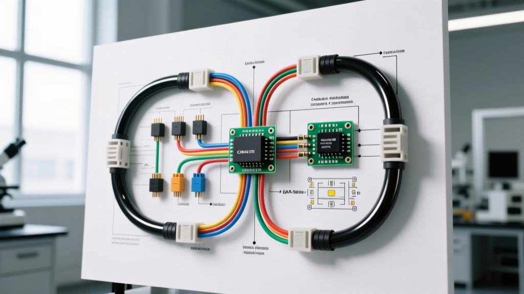
Introduction to Halo Headlight Electrical Architecture
Integrating aftermarket halo rings (Angel Eyes) into modern vehicle lighting systems requires far more than splicing into a parking light circuit. When referencing a comprehensive wiring diagram for halo headlights, technicians must account for Pulse Width Modulation (PWM) Daytime Running Light (DRL) signals, Body Control Module (BCM) current monitoring, and the distinct electrical requirements of Cold Cathode Fluorescent Lamp (CCFL) versus modern Light Emitting Diode (LED) topologies. This advanced technical guide details the precise relay logic, PWM decoding, and wire gauge specifications required to retrofit halo rings safely without triggering hyperflash, CAN-bus fault codes, or thermal damage to the factory headlight harness.
Core Wiring Diagram for Halo Headlights: The PWM Relay Harness
Directly wiring halo rings to the factory low-beam or DRL circuit is a critical failure point on modern vehicles (e.g., GM Alpha platform, Ford S550). Factory BCMs utilize high-frequency PWM (typically 100Hz to 500Hz) to dim the DRLs. Standard aftermarket halo drivers cannot process this square wave, resulting in severe flickering or immediate driver burnout. The correct architecture requires an inline PWM decoder paired with a dedicated 12V relay harness.
Schematic Logic Flow
- Power Source: Direct connection to the battery positive terminal via an inline MAXI fuse.
- Trigger Source: Tapped into the factory low-beam positive wire (e.g., H11 or 9005 connector) using a T-tap or pos-i-tap.
- PWM Decoding: The factory trigger signal passes through a PWM-to-DC converter module. This module reads the duty cycle of the factory DRL signal and outputs a steady, reduced DC voltage (usually 6V-8V) for DRL mode, and full 12V when the low beams are fully energized.
- Relay Actuation: The decoded signal triggers the relay coil, switching high-current battery power to the halo LED drivers or CCFL inverters.
Bosch-Style 5-Pin Relay Pinout Configuration
| Pin Number | Function | Wire Color (Standard) | Connection Point |
|---|---|---|---|
| 30 | Common / Power In | Red (10 AWG TXL) | Battery Positive (via 15A Fuse) |
| 87 | Normally Open (Load) | Red (10 AWG TXL) | Halo Driver/Inverter 12V Input |
| 87a | Normally Closed | Not Used | Isolated / Capped |
| 86 | Coil Positive (Trigger) | Yellow (18 AWG GXL) | PWM Decoder Output |
| 85 | Coil Negative (Ground) | Black (18 AWG GXL) | Chassis Ground / Battery Negative |
Wire Gauge (AWG) and Current Draw Calculations
Selecting the correct wire gauge is dictated by the specific halo technology. According to AutoShop101 Electrical Fundamentals, voltage drop over distance must be kept below 3% for sensitive LED drivers to prevent undervoltage lockouts.
| Halo Technology | Operating Voltage | Current Draw (Per Ring) | Driver/Inverter Type | Recommended Harness AWG |
|---|---|---|---|---|
| CCFL (Legacy) | 12V DC Input / ~1000V AC Output | 10mA - 15mA | High-Frequency AC Inverter | 22 AWG (Low Current) |
| Standard LED (SMD) | 9V - 16V DC | 350mA - 500mA | Constant Current Buck Driver | 18 AWG (Standard) |
| High-Power COB LED | 9V - 16V DC | 800mA - 1.2A | Constant Current Driver w/ Heat Sink | 16 AWG (High Current) |
Note: CCFL inverters generate lethal high-frequency AC voltage on the output side. The white/silver output wires must be routed away from the metal headlight housing to prevent arcing and dielectric breakdown.
CAN-Bus Integration and Load Resistor Matrices
On vehicles equipped with CAN-bus bulb-out detection (e.g., BMW, Audi, late-model Dodge), the BCM measures the current draw of the lighting circuit. Because LED halos draw significantly less current than the factory incandescent parking lights they often replace, the BCM interprets this as a blown bulb, triggering a dashboard warning and cutting power to the circuit (a phenomenon known as 'cold diagnostics' pulsing).
Calculating Load Resistor Requirements
To bypass this, the wiring diagram for halo headlights must incorporate load resistors wired in parallel with the halo trigger circuit. The goal is to simulate the 5W to 21W draw of a standard W5W or 1157 bulb.
- Target Wattage: 10 Watts (Safe margin for 5W parking light circuits).
- Formula: R = V² / P. Assuming a 14.4V alternator output: R = (14.4)² / 10 = 20.7 Ohms.
- Component Selection: Use a 22 Ohm, 25W aluminum-housed power resistor. Mount the resistor to a metal chassis point using thermal paste, as it will dissipate significant heat during DRL operation.
For advanced diagnostics on modern multiplexed networks, refer to the Diode Dynamics Technical Guides regarding PWM decoder compatibility with specific BCM frequencies.
Troubleshooting Halo Flicker and BCM Fault Codes
When the halo rings exhibit erratic behavior, use the following diagnostic decision tree before replacing hardware:
Symptom: Halos Flicker Rapidly in DRL Mode
- Cause: Factory BCM is utilizing high-frequency PWM dimming; halo driver lacks internal smoothing capacitors.
- Fix: Install an inline PWM DRL Decoder (Capacitor Bank) between the factory trigger wire and the halo driver input. Ensure the decoder is rated for the specific Hz frequency of the vehicle (e.g., VW/Audi often use 1kHz+, requiring specialized high-speed decoders).
Symptom: Halos Turn Off After 30 Seconds of Operation
- Cause: BCM Cold Diagnostics. The BCM sends a rapid 10ms pulse every few seconds to check circuit continuity. The halo driver interprets this as a power-on signal, charges its capacitors, and the BCM detects an abnormal inrush current spike, shutting the circuit down.
- Fix: Wire a 50V 4700µF electrolytic capacitor in parallel at the halo driver input to absorb the diagnostic pulses, or utilize a dedicated CAN-bus error eliminator module.
Symptom: One Halo Ring is Dim or Shows Color Shift
- Cause: Voltage drop across an undersized wire run or a corroded chassis ground. LED color temperature shifts visibly when voltage drops below 11.5V.
- Fix: Perform a voltage drop test across the ground wire. A reading above 0.1V indicates a poor ground. Sand the chassis contact point to bare metal, apply dielectric grease, and secure with a star washer and M6 bolt.
Step-by-Step Harness Routing and Grounding Protocols
Proper routing ensures the longevity of the halo wiring harness, particularly given the extreme thermal cycling inside a headlight housing.
- Headlight Baking and Opening: Heat the headlight assembly to 250°F (121°C) for 15 minutes to soften the butyl rubber sealant. Carefully separate the lens.
- Internal Routing: Route the halo power wires through the existing dust cap grommet. Never drill the polycarbonate lens or housing without using a rubber grommet, as moisture ingress will destroy the internal reflector bowl.
- Driver Placement: Mount the LED drivers or CCFL inverters outside the headlight housing. The ambient temperature inside a sealed headlight can exceed 180°F (82°C), which exceeds the thermal limits of most driver electrolytic capacitors.
- Loom and Protection: Wrap all external harness wiring in Tesa 51036 PET cloth tape. Avoid corrugated plastic split-loom in engine bays, as it traps moisture and accelerates galvanic corrosion on copper strands.
- Grounding: Consolidate all halo ground wires into a single 10 AWG pigtail and terminate it to a factory engine block ground stud or a dedicated chassis point using a ring terminal crimped with a ratcheting crimper to ensure a gas-tight connection.
References and SAE Standards
When designing or modifying automotive lighting circuits, adherence to established engineering standards is critical for safety and compliance. For comprehensive relay specifications and inductive kickback suppression, consult Bosch Mobility Solutions Relay Documentation. Furthermore, all wire insulation selections should meet SAE J1128 standards for low-tension primary cable, ensuring resistance to engine oil, coolant, and extreme under-hood temperatures.