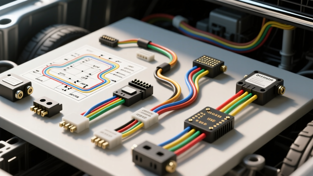
System Architecture and Control Logic
When analyzing the power door lock wiring diagram for the GM GMT800 platform (1999-2006 Silverado, Sierra, Tahoe, and Suburban), technicians must understand that this system operates on a hardwired analog relay architecture rather than a multiplexed LIN-bus network found in newer vehicles. The Body Control Module (BCM) serves as the central logic gateway, processing inputs from the interior door lock switches, the keyless entry receiver, and the automatic lock/unlock logic tied to the Powertrain Control Module (PCM) via the Class 2 serial data bus.
The BCM contains internal high-current relays that manage polarity reversal to the reversible DC motors housed within each door latch assembly. Because the actuators draw significant stall current during the mechanical binding phase of the latch mechanism, the wiring harness must maintain strict voltage drop tolerances. According to SAE J1128 standards for low-tension primary cable, the insulation and conductor sizing must withstand under-hood and door-jamb thermal cycling without degrading the circuit's overall resistance.
OEM Power Door Lock Wiring Diagram Reference
The following matrix details the primary control circuits originating from the BCM Connector C1 (Grey) and routing through the driver-side A-pillar rubber pass-through boot to the door harness. This data is critical for pinout testing and continuity verification.
| Circuit ID | Wire Color | AWG | BCM C1 Cavity | Function / Destination |
|---|---|---|---|---|
| 75 | Dark Blue (DK BLU) | 18 | Pin 45 | Lock Relay Output (To all door actuators) |
| 748 | Light Blue (LT BLU) | 18 | Pin 46 | Unlock Relay Output (To all door actuators) |
| 150 | Black (BLK) | 16 | Pin 19 | Primary Module Ground (Splice Pack SP102) |
| 140 | Orange (ORG) | 12 | Pin 20 | Constant Battery Feed (From Underhood Fuse 47) |
| 742 | Tan (TAN) | 20 | Pin 58 | Driver Door Ajar / Lock Cylinder Switch Input |
Note: Wire colors and circuit IDs are specific to the 2003-2006 GMT800 facelift harness. Earlier 1999-2002 models may utilize external lock/unlock relays located in the instrument panel junction block rather than internal BCM relays.
Actuator and Relay Electrical Specifications
Proper diagnosis of the power door lock wiring diagram requires baseline electrical specifications. The door lock actuators are permanent-magnet reversible DC motors integrated into the latch housing. Testing these components requires a digital multimeter (DMM) capable of capturing peak inrush current.
| Specification Parameter | Min / Max Value | Diagnostic Notes |
|---|---|---|
| Actuator Coil Resistance | 2.5 - 4.0 Ohms | Measured across the lock/unlock terminals at the actuator pigtail. |
| Stall Current (Inrush) | 3.2A - 4.5A | Peak draw during the final 50ms of latch mechanical engagement. |
| Operating Voltage Threshold | 9.5V Minimum | Below 9.5V, the BCM internal thermal protection may inhibit the relay. |
| Relay Coil Resistance (BCM) | 75 - 90 Ohms | Internal BCM logic side; failure requires BCM replacement. |
| Max Allowable Voltage Drop | 0.2V (Power/Ground) | Tested under load while actuating the lock switch. |
Retained Accessory Power (RAP) Integration
A unique feature of the GM GMT800 power door lock circuit is its integration with the Retained Accessory Power (RAP) system. The BCM monitors the ignition cylinder ring antenna and the RAP relay feed (Circuit 439, Yellow wire). When the ignition is turned off, the BCM maintains power to the window and door lock circuits for exactly 10 minutes, or until the driver's door is opened. If you are tracing a dead power door lock circuit where the locks only fail to operate with the key out of the ignition and the door closed, the fault is rarely in the door harness itself. Instead, diagnose the RAP relay located in the instrument panel fuse block, as this relay provides the secondary power path for the switch illumination and logic wake-up signals.
Diagnostic Decision Tree: Lock/Unlock Failures
When utilizing the power door lock wiring diagram to isolate a fault, follow this structured diagnostic sequence to avoid unnecessary component replacement. For comprehensive wiring schematics and connector end-views, technicians should consult official OEM service documentation archives rather than relying on aftermarket simplified charts.
- Symptom: All doors fail to lock/unlock from driver switch, but Remote Keyless Entry (RKE) works.
- Cause: Switch ground failure or BCM input circuit fault.
- Action: Test Circuit 150 (Black) at the switch connector for continuity to ground. Check BCM C1 Pin 52 for switch signal voltage drop when depressed.
- Symptom: Driver door locks/unlocks, but passenger doors do not respond.
- Cause: Open circuit in the parallel splice pack (SP205) located under the driver-side carpet, near the kick panel.
- Action: Peel back the carpet and inspect the sealed splice pack for corrosion or a pushed-out terminal.
- Symptom: Door locks cycle rapidly or BCM clicks repeatedly without motor movement.
- Cause: High resistance in the actuator motor or binding mechanical linkage causing the BCM's internal thermal overload protection to trip and reset.
- Action: Disconnect the actuator at the door jamb boot. Apply 12V directly from a fused jumper wire. If the motor draws over 5.0A, replace the latch assembly.
Common Failure Modes and Harness Repair Protocols
The most pervasive failure point in the GMT800 power door lock wiring diagram is the driver-side door jamb pass-through boot. Every time the door is opened and closed, the 18 AWG Dark Blue and Light Blue wires undergo severe flexion. Over years of thermal cycling, the copper strands work-harden, fracture, and eventually short against one another or the chassis ground. This results in a blown BCM internal trace or a dead short that trips the underhood fuse.
When repairing these circuits, standard electrical tape and butt connectors are strictly prohibited. As outlined in professional automotive body electrical repair guidelines, technicians must use cross-linked polyethylene (XLPE) insulated wire matching SAE J1128 specifications. Repairs must be executed using open-barrel crimp tools with adhesive-lined, dual-wall heat shrink tubing to prevent moisture ingress into the splice joint. Furthermore, if the Dark Blue and Light Blue wires have shorted together and sent 12V back into the BCM's low-side driver, the BCM's internal micro-relay contacts may be welded shut. In such cases, continuity testing between the lock and unlock circuits at the BCM connector with the module unplugged will reveal a dead short, mandating BCM replacement and harness repair.