Decoding the Wiring Diagram for Electric Scooter Upgrades
When upgrading high-performance electric scooters like the Kaabo Wolf King, Dualtron Thunder, or custom QS Motor builds, relying on a generic wiring diagram for electric scooter systems is a recipe for melted phase wires and fried hall sensors. As an automotive and micro-mobility electrical specialist, I evaluate scooter wiring harnesses not just by their layout, but by their adherence to automotive-grade standards like SAE J1128 for low-tension primary cables. This guide compares the dominant controller architectures and helps you select the correct wiring schematic and harness components for your build.
Controller Architecture Comparison: VESC vs. Sine Wave vs. Square Wave
The core of any electric scooter wiring diagram revolves around the motor controller. Selecting the right controller dictates your harness complexity, pinout requirements, and thermal management.
1. VESC (Vedder Electronic Speed Controller)
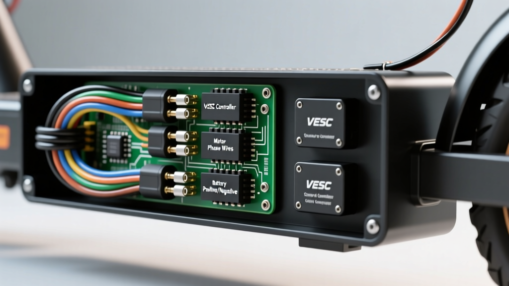
Preferred for custom builds and extreme performance (e.g., 72V systems pushing 150A+). VESC wiring diagrams rely on UART or CAN-bus communication for displays, eliminating the need for bulky analog gauge clusters. Phase wires require minimum 8 AWG silicone jacket wire to handle peak burst currents without voltage sag.
2. Sine Wave (FOC - Field Oriented Control)
Standard on premium OEM scooters (Zero 10X, NAMI Burn-E). The wiring diagram for electric scooter FOC systems includes a 3-wire hall sensor array and a 5-wire throttle/brake integration. They run cooler than square wave but require precise hall sensor phasing (120-degree separation).
3. Square Wave
Found in budget and older models. The wiring harness is simpler, often lacking active regenerative braking lines. However, the abrupt current delivery causes higher thermal stress on the phase wire crimps, necessitating heavy-duty heat shrink and die-crimped Anderson connectors rather than soldered joints.
Wire Gauge (AWG) and Connector Selection Matrix
A common failure point in scooter wiring is undersized harnesses. Using 12 AWG wire on a 100A continuous draw system will result in insulation melt. Refer to this selection matrix when interpreting your wiring diagram for electric scooter power distribution.
| Circuit Type | Max Continuous Current | Recommended AWG | Connector Standard | Insulation Type |
|---|---|---|---|---|
| Main Battery to Controller | 80A - 150A | 8 AWG or 6 AWG | XT90-S (Anti-Spark) / Anderson SB50 | Silicone (200C rated) |
| Motor Phase Wires (U, V, W) | 150A - 250A Peak | 10 AWG or 8 AWG | 4.2mm Bullet / 5.5mm Bullet | Silicone (High Flex) |
| Hall Sensor / Throttle | Less than 1A | 22 AWG or 20 AWG | JST-SM (3-pin / 5-pin) | PVC / Teflon |
| Lighting / Accessories | 5A - 10A | 16 AWG | Deutsch DT (2-pin waterproof) | Cross-linked PE |
Hall Sensor Pinout and Signal Calibration
The most critical low-voltage section of the wiring diagram for electric scooter motors is the hall sensor harness. Incorrect pinouts will cause the motor to stutter, overheat, or fail to spin, often blowing the controller's internal 5V voltage regulator.
Standard QS Motor and generic hub motor hall sensors follow a 5-pin JST-SM layout:
- Pin 1 (Red): +5V VCC (Must be regulated; connecting to 12V or battery positive will instantly destroy the hall ICs).
- Pin 2 (Black): Ground (GND).
- Pin 3 (Yellow): Hall Signal A (Phase U alignment).
- Pin 4 (Green): Hall Signal B (Phase V alignment).
- Pin 5 (Blue): Hall Signal C (Phase W alignment).
Expert Troubleshooting Tip: If your scooter displays a Hall Error on generic LCDs, use a multimeter to back-probe the JST connector while spinning the wheel. You should see a clean square wave toggling between 0V and 5V on the signal pins. A flat 2.5V reading indicates a blown internal pull-up resistor in the controller.
Throttle and Brake Integration: Analog vs. Digital
When selecting a wiring harness, you must match the throttle type specified in the controller's schematic. Most modern sine wave controllers utilize a 3-wire analog hall-effect throttle.
Analog Throttle Pinout
- Red: +5V Reference
- Black: Ground
- White/Green: Signal Return (0.8V at rest, 4.2V at full throttle)
If your wiring diagram for electric scooter upgrades shows a 2-wire throttle, it is likely a potentiometer-based or magnetic reed switch setup, which requires a different pull-up resistor configuration on the controller's PCB. Always verify the controller's Throttle Low Voltage and Throttle High Voltage parameters via the programming software (such as the VESC Tool) to prevent unintended acceleration upon startup.
Battery Management System (BMS) Communication Integration
In advanced electric scooter platforms, the wiring diagram for electric scooter systems must account for BMS-to-Controller communication. This is critical for preventing over-discharge and managing thermal throttling. Modern smart BMS units communicate via RS485 or CAN-bus protocols.
CAN-Bus Wiring Standard:
- CAN-H (High): Typically Yellow or White wire. Terminates with a 120-ohm resistor at the end of the bus.
- CAN-L (Low): Typically Green or Yellow/Black wire.
- Shield/Ground: Bare copper drain wire connected to chassis ground at one single point to prevent ground loops.
If your controller does not support native CAN-bus, you must rely on the BMS's analog discharge cutoff. This requires wiring the BMS's main discharge negative directly to the controller's main negative, which means the BMS MOSFETs must be rated for the controller's peak current draw. Always check the Anderson Power Products SB50 and main fuse ratings to ensure they exceed the BMS continuous discharge limit by at least 20%.
Anti-Spark and Pre-Charge Circuit Selection
Plugging a fully charged 72V battery directly into a controller with massive capacitive input filters will result in a violent spark. This spark degrades the copper contacts of your XT90 connectors and can weld the main power switch shut. A proper wiring diagram for electric scooter builds incorporates an anti-spark pre-charge circuit.
There are two primary methods to select and wire this protection:
1. XT90-S Anti-Spark Connectors
The simplest selection for builds under 100A. The XT90-S features a built-in resistor that slowly charges the controller capacitors before the main high-current pins make contact. However, these resistors can fail if the plug is inserted too slowly, causing the resistor to overheat and melt the plastic housing.
2. External Pre-Charge Resistor and Relay
For high-current builds (150A+), the wiring diagram should include a heavy-duty automotive relay wired in parallel with a 470-ohm, 10-watt pre-charge resistor. When the ignition key is turned, the low-current circuit powers the resistor, charging the caps over 2-3 seconds. A secondary switch then engages the main relay, bypassing the resistor. This is the most robust method and mirrors heavy EV architecture.
Regenerative Braking and Brake Light Switches
Integrating regenerative braking requires precise wiring of the brake lever hall sensors or microswitches. Most sine wave controllers feature dedicated E-ABS or Low-Level Brake inputs.
Wiring the Brake Light and E-ABS Simultaneously:
A common mistake is wiring the 12V brake light bulb in series with the controller's 5V brake signal line. This will feed 12V back into the controller's logic board, instantly frying the microprocessor. Instead, use a standard automotive 5-pin 12V relay. The brake lever microswitch triggers the relay coil. The relay's Normally Open (NO) contact simultaneously switches the 12V brake light AND pulls the controller's brake signal pin to ground (activating E-ABS). This isolation is a mandatory safety feature in any professional wiring diagram for electric scooter systems.
Lighting and Step-Down Converter Wiring
High-performance scooters operate on 52V, 60V, or 72V nominal battery packs. Running LED headlights or brake lights directly off the main pack will destroy them. The wiring diagram must include a DC-DC step-down converter (typically 72V to 12V).
When wiring the lighting harness, use automotive-grade Deutsch DT connectors for all external lighting connections. These connectors feature silicone rear grommets and copper-nickel crimp barrels that resist the severe vibration and water ingress typical in scooter steering stems and swingarms. Avoid generic Molex or JST connectors for exterior lighting, as their friction-fit pins will corrode and fail within months of exposure to road salt and moisture.
Summary: Selecting Your Harness
Choosing the correct wiring diagram for electric scooter builds requires matching the controller architecture (VESC vs. Sine Wave) with appropriately gauged, high-temperature silicone wiring and vibration-resistant connectors. Never compromise on phase wire crimps or hall sensor shielding. By adhering to automotive electrical standards and verifying pinouts with a multimeter before applying main pack voltage, you ensure a reliable, high-performance micro-mobility platform.