Introduction to Commercial Powerplant Integration
When integrating a commercial powerplant into a custom UTV, industrial sweeper, heavy-duty groundskeeping vehicle, or auxiliary power unit, understanding the exact Briggs and Stratton engine wiring diagram is critical for operational reliability. Unlike standard automotive alternators that utilize an internal voltage regulator and a DC excitation field, Briggs & Stratton Vanguard V-Twin and commercial single-cylinder engines rely on a permanent magnet flywheel stator paired with an external rectifier/regulator module. This technical specification reference breaks down the core electrical architecture, wire color codes, AWG requirements, and OEM connector pinouts necessary for proper chassis integration and long-term electrical health.
Core Electrical Architecture: Stator and Rectifier
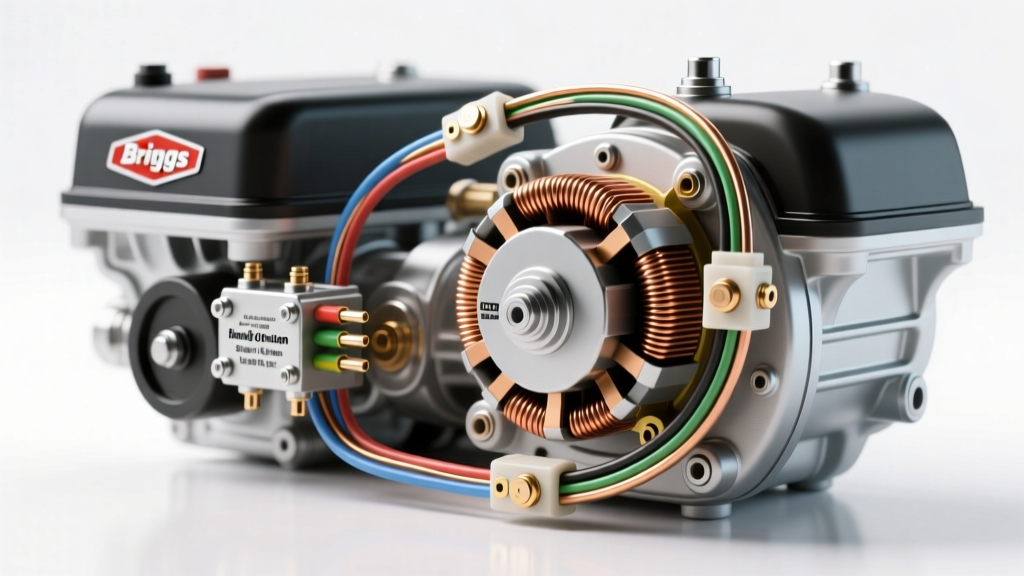
The charging system on a Briggs & Stratton commercial engine begins under the flywheel. The stator consists of copper wire coils wrapped around an iron core. As the flywheel's permanent magnets rotate past the stator poles, an alternating current (AC) is induced. This raw AC voltage is highly variable, scaling directly with engine RPM. At idle (approx. 1400 RPM), the stator may output only 14V AC, but at the governed operating speed of 3600 RPM, a high-output 33-Amp stator will produce between 28V and 35V AC.
Because the vehicle's chassis, battery, and electronic control modules (ECMs) require a stable 12V to 14.4V DC supply, the AC output must be routed through a Voltage Regulator/Rectifier (VRR). The VRR utilizes a bridge rectifier to convert the AC waveform into pulsating DC, and a Zener diode-based shunt regulator to bleed off excess voltage as heat, maintaining a safe charging voltage of approximately 14.1V to 14.7V DC.
Stator Output Specifications & Wire Colors
According to Briggs & Stratton Vanguard Service Documentation, proper wire gauge selection is vital to prevent voltage drop and harness fires. The following table outlines the standard wiring specifications for the stator-to-rectifier circuit.
| Circuit Path | Wire Color | AWG Size | Function | Expected Voltage (at 3600 RPM) |
|---|---|---|---|---|
| Stator AC Output 1 | Yellow or White | 14 AWG | Carries raw AC to VRR | 28V - 35V AC |
| Stator AC Output 2 | Yellow or White | 14 AWG | Carries raw AC to VRR | 28V - 35V AC |
| VRR DC Output | Red | 10 AWG | Regulated DC to Battery | 14.1V - 14.7V DC |
| VRR Ground | Black | 10 AWG | Chassis/Engine Block Ground | 0V (Continuity to Block) |
Note: Never run the engine with the battery disconnected. The battery acts as a massive capacitor that smooths the pulsating DC waveform. Without it, voltage spikes can exceed 40V DC, instantly destroying the VRR's internal diodes and potentially frying sensitive vehicle ECMs.
Magnatron Ignition & Kill Circuit Routing
Briggs & Stratton utilizes the Magnatron solid-state ignition system. This system eliminates mechanical breaker points, relying on a Hall-effect sensor or magnetic pickup to trigger the ignition coil. The primary coil charges and collapses to fire the spark plug. A common point of confusion for automotive technicians adapting these engines is the kill circuit logic.
In most automotive applications, a wire supplies 12V to the ignition coil to run the engine. In the Briggs and Stratton engine wiring diagram, the logic is inverted. The Magnatron coil fires continuously as long as the kill wire is isolated from ground. To stop the engine, the ignition switch or safety interlock module grounds the kill wire (typically White or Green, 18 AWG). This ground path shunts the primary coil's magnetic field, preventing the secondary winding from generating high voltage.
Troubleshooting the Ignition Ground Path
If an engine fails to shut off when the key is turned to the 'OFF' position, the issue is rarely a failed ignition coil. Instead, it is almost always an open circuit in the kill wire path. Use a digital multimeter (DMM) to test for continuity between the engine harness kill wire pin and the chassis ground when the key is in the OFF position. Common failure points include corroded OEM Molex connector pins, broken safety interlock switch contacts, or a severed wire near the engine vibration dampeners.
OEM Engine-to-Chassis Harness Connector Pinout
For commercial vehicle integrations, the engine harness terminates in a multi-pin connector (often a 9-pin or 14-pin Molex MX150 or Deutsch DT series) that mates with the vehicle's chassis harness. Adhering to SAE J1128 standards for low-tension primary cable, the following pinout represents a standard 9-pin Vanguard V-Twin commercial configuration.
| Pin | Circuit Function | Wire Color | AWG | Connector Terminal Type |
|---|---|---|---|---|
| 1 | Battery B+ (Main Power) | Red | 10 AWG | Heavy Duty Ring/Spade |
| 2 | Starter Solenoid Trigger | Purple or Red/White | 16 AWG | Standard Male Blade |
| 3 | Ignition Kill (Ground to Stop) | White or Green | 18 AWG | Standard Male Blade |
| 4 | Stator AC Output 1 | Yellow | 14 AWG | Standard Male Blade |
| 5 | Stator AC Output 2 | Yellow | 14 AWG | Standard Male Blade |
| 6 | PTO Clutch B+ Supply | Red/White | 14 AWG | Heavy Duty Blade |
| 7 | Oil Pressure Sender Signal | Gray | 18 AWG | Standard Male Blade |
| 8 | Main Chassis Ground | Black | 10 AWG | Heavy Duty Ring |
| 9 | Spare / Temp Sensor | Blue | 18 AWG | Standard Male Blade |
PTO Clutch Integration and Flyback Diode Protection
In vehicles equipped with auxiliary hydraulic pumps or commercial mowers with cutting decks, an electric Power Take-Off (PTO) clutch is engaged via a 12V DC electromagnetic coil. Warner or Ogura PTO clutches typically draw between 2.5A and 4.0A at 12V DC. While 14 AWG wire is sufficient for the current load, the inductive nature of the clutch coil poses a severe threat to the engine's electrical system.
When the PTO switch is turned off, the collapsing magnetic field in the clutch coil generates a massive reverse voltage spike (inductive kickback), often exceeding 100V for a fraction of a millisecond. If this spike travels back through the chassis harness, it will instantly punch through the silicon junctions in the Briggs & Stratton VRR, destroying the charging system. To prevent this, a flyback diode (such as a 1N5408 3-Amp diode) must be wired in parallel across the PTO clutch terminals, with the diode's cathode (stripe) facing the 12V positive supply. This creates a safe recirculation loop for the inductive spike, protecting the rectifier.
Starter Motor Solenoid Voltage Drop Testing
The starter circuit on a commercial V-Twin utilizes a remote-mounted solenoid to handle the high inrush current (often 150A to 250A) required to crank the high-compression engine. The ignition switch only carries the low-current trigger signal (Pin 2 on the harness connector). If the starter solenoid clicks but the engine does not crank, perform a voltage drop test across the solenoid's main terminals while the key is held in the 'START' position. A healthy solenoid and clean battery cables will show a voltage drop of less than 0.5V. A reading above 1.0V indicates pitted internal solenoid contacts or severe corrosion at the battery lugs, requiring immediate replacement to prevent localized melting of the automotive wire insulation.
Summary of Best Practices
Successfully adapting a Briggs and Stratton engine wiring diagram into a vehicular or industrial chassis requires strict adherence to AWG sizing, proper grounding methodologies, and inductive spike protection. Always use dielectric grease on all multi-pin Molex and Deutsch connectors to prevent moisture intrusion and galvanic corrosion. By respecting the unique AC-to-DC architecture of the flywheel stator and the inverted logic of the Magnatron kill circuit, fleet technicians and custom builders can ensure maximum uptime and electrical reliability.