Introduction to 3-Prong Headlight Circuit Architecture
For decades, the 3 prong headlight wiring diagram has served as the foundational lighting schematic for classic American muscle cars, vintage trucks, and early import vehicles. Whether you are restoring a 1969 Chevrolet Camaro with factory H6024 sealed beams or retrofitting a classic Ford F-100 with modern H4 halogen bulbs, understanding the precise electrical topology is critical. Modern lighting upgrades demand significantly more current than original equipment manufacturer (OEM) wiring was designed to carry. This advanced technical deep dive explores OEM pinouts, the physics of voltage drop in aging harnesses, and the exact relay upgrade schematics required to deliver optimal lumens without melting your bulkhead connector or dimmer switch.
Decoding the OEM 3 Prong Headlight Wiring Diagram
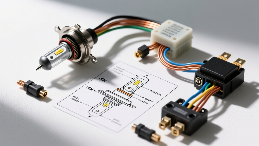
The traditional sealed beam system relies on a simple 3-terminal architecture. The physical prongs on the back of an H6014 or H6024 sealed beam unit correspond directly to the ground, low beam filament, and high beam filament. When transitioning to an H4 (9003/HB2) halogen or LED conversion, the 3-prong geometry remains identical, but the electrical characteristics change drastically. H4 halogen bulbs draw approximately 55W on low beam and 60W on high beam per side, compared to the 35W/50W draw of older incandescent sealed beams. This 20-30% increase in amperage is where OEM wiring harnesses begin to fail.
Pin Configuration & Wire Color Matrix
While wire colors vary by manufacturer and model year, the functional topology remains consistent across almost all vintage 3-prong applications. Below is the standard reference matrix for GM and Ford applications from the 1960s through the early 1980s.
| Function | OEM Sealed Beam Prong | H4 Bulb Pin | Typical GM Wire Color | Typical Ford Wire Color | Upgraded Relay Feed |
|---|---|---|---|---|---|
| Ground | Prong 1 (Shell) | Pin 1 | Black | Black | 12 AWG Black (Direct to Chassis) |
| Low Beam | Prong 2 | Pin 2 | Tan | Red/Black Stripe | 12 AWG (From Relay 87) |
| High Beam | Prong 3 | Pin 3 | Light Green | Green/Black Stripe | 12 AWG (From Relay 87) |
The Physics of Voltage Drop in Vintage Harnesses
The most common failure mode in classic vehicle lighting is not a blown bulb, but severe voltage drop. OEM manufacturers typically routed headlight power from the battery, through the firewall bulkhead connector, into the cabin to the headlight switch, back out through the firewall to the dimmer switch on the floorboard, and finally to the headlights. This circuit often exceeds 25 feet of 16 AWG or 18 AWG copper wire.
According to SAE International standards and basic Ohm's Law, pushing 10 amps (two 60W high beams at 12V) through 25 feet of 16 AWG wire results in a voltage drop of nearly 2.5 volts. If your alternator is outputting 14.2V, the bulb only receives 11.7V. Halogen bulbs require a minimum of 13.2V to achieve their rated color temperature and lumen output. Running an H4 bulb at 11.7V shifts the light spectrum to a dim, yellow hue and drastically reduces forward illumination. Upgrading the 3 prong headlight wiring diagram with a dedicated relay harness bypasses the OEM switches and bulkhead connectors, delivering full alternator voltage directly to the bulb.
Advanced ISO Relay Upgrade Schematic
To properly modernize a 3-prong system, you must implement a dual-relay architecture. Using standard Bosch-style ISO mini relays ensures high-current switching capability while keeping the trigger current low enough to safely pass through the vintage floor dimmer switch and steering column stalk.
Component Specifications & AWG Requirements
| Component | Specification | Wire Gauge (AWG) | Terminal Type |
|---|---|---|---|
| Main Power Feed | 30A MAXI Fuse | 10 AWG | Ring Terminal (5/16') |
| Relay Power (Pin 30) | ISO Mini Relay | 12 AWG | Fused Spade |
| Relay Trigger (Pin 86) | From OEM Dimmer | 16 AWG | Quick Disconnect |
| Relay Ground (Pin 85) | Chassis Ground | 14 AWG | Ring Terminal (1/4') |
| Load Output (Pin 87) | To Headlight Pigtail | 12 AWG | H4 Ceramic Plug |
Step-by-Step Relay Wiring Topology
- Main Battery Feed: Run a 10 AWG red wire from the positive battery terminal (or alternator output stud) to a 30A MAXI fuse holder mounted within 8 inches of the battery. From the fuse, split the feed into two 12 AWG wires using a sealed heat-shrink butt splice.
- Relay Pin 30 (Normally Open Input): Connect the split 12 AWG feeds to Pin 30 on both the Low Beam relay and the High Beam relay.
- Relay Pin 87 (Switched Output): Run 12 AWG wire from Pin 87 of the Low Beam relay to the Pin 2 (Low Beam) terminals of both left and right headlight pigtails. Repeat for the High Beam relay to Pin 3 of the headlights.
- Relay Pin 85 (Coil Ground): Ground Pin 85 on both relays to a clean, bare-metal point on the inner fender or radiator core support using a star washer and 14 AWG wire.
- Relay Pin 86 (Coil Trigger): Tap into the OEM low beam and high beam wires after the floor dimmer switch. Connect the OEM low beam wire to Pin 86 on the Low Beam relay, and the OEM high beam wire to Pin 86 on the High Beam relay. The OEM switch now only carries the 150mA trigger current for the relay coils, eliminating heat buildup and bulkhead connector melting.
Connector Terminal Crimping & Weatherproofing
The environment at the front of a vehicle is hostile to electrical connections. Standard vinyl insulated crimps will wick moisture via capillary action, leading to galvanic corrosion and green copper oxide buildup inside the 3-prong plug. For the headlight pigtail connectors, always use unsealed, open-barrel nickel-plated brass terminals crimped with a precision ratcheting crimper (such as the TE Connectivity AMP Superseal or equivalent). After crimping, slide a piece of dual-wall adhesive-lined heat shrink tubing over the wire barrel and apply heat until the inner polyamide adhesive extrudes slightly from the edges. This creates a hermetic seal that prevents moisture ingress. Furthermore, always use ceramic 3-prong pigtail sockets rather than plastic ones; H4 bulbs generate immense heat at the base, and plastic sockets will become brittle and melt over time, altering the pin tension and causing arcing.
Troubleshooting Ground Loops & Backfeed
When modifying a 3 prong headlight wiring diagram, technicians frequently encounter a specific anomaly: the high beam indicator light on the dashboard glows dimly when the low beams are on, or the low beams flicker when the high beams are engaged. This is known as backfeed, and it is almost exclusively caused by a high-resistance ground at the headlight socket.
In a 3-prong system, the ground circuit is shared between the low and high beam filaments. If the primary ground wire (Prong 1) has high resistance due to corrosion or a poor chassis connection, the current from the energized filament will seek an alternative path to ground. It will travel backward through the opposing filament, through the dimmer switch, and into the dashboard indicator bulb, using the indicator bulb's ground to complete the circuit. To diagnose this, perform a voltage drop test across the ground prong of the headlight socket and a known good engine block ground with the headlights energized. A reading above 0.1V indicates a faulty ground. The definitive fix is to bypass the OEM ground wire entirely by soldering a new 12 AWG ground wire directly to the metal shell of the sealed beam ring or the H4 socket base, routing it directly to the radiator core support.
Authoritative References & Standards
- For federal compliance and lumen output regulations regarding sealed beam and replaceable bulb headlamp systems, refer to the National Highway Traffic Safety Administration (NHTSA) Federal Motor Vehicle Safety Standard (FMVSS) 108.
- For detailed classic vehicle relay harness schematics and bulkhead connector current limits, consult the technical documentation provided by Painless Performance Products.
- Wire resistance calculations and automotive copper stranding specifications are based on SAE International standard J1128 for low-tension primary cable.