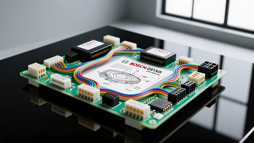
Understanding the Bosch DS150i 5-Wire Wideband Architecture
When integrating high-performance engine management systems, accessing an accurate Bosch DS150i wiring diagram is only the first step. The Bosch DS150i (based on the legendary LSU 4.9 wideband lambda architecture) is a precision electrochemical device, not a simple resistive sensor. It utilizes a dual-cell design: a Nernst reference cell and an oxygen pump cell, paired with an integrated ceramic heater. Because the sensor operates by measuring the micro-current required to maintain a stoichiometric balance inside the diffusion barrier, even minor wiring errors will result in catastrophic signal drift, blown ECU driver circuits, or permanently destroyed sensor elements.
This guide bypasses basic installation fluff and focuses strictly on the most common, destructive wiring mistakes made by hobbyists and professional tuners alike, alongside critical safety warnings to protect your powertrain control module (PCM) and the sensor itself.
Bosch DS150i Pinout & Wiring Diagram Reference
Before diving into failure modes, you must verify your harness against the OEM Bosch specification. The DS150i utilizes a specific 5-pin connector. Below is the definitive pinout and wire gauge requirement chart based on Bosch Motorsport technical datasheets.
| Pin | Wire Color | Function | Min. AWG Spec | Routing / Shielding Notes |
|---|---|---|---|---|
| 1 | White | Heater Ground | 16 AWG | Direct to ECU PWM ground or dedicated sensor ground bus. |
| 2 | White | Heater +12V (PWM) | 16 AWG | Must handle 2.5A+ peak current. Do not use constant 12V. |
| 3 | Grey | Calibration Resistor | 22 AWG | CRITICAL: Contains laser-trimmed resistor. Do not cut or splice. |
| 4 | Black | Pump Cell + | 22 AWG | Must use shielded twisted pair with Pin 5. |
| 5 | Red / Yellow | Pump Cell - / Reference | 22 AWG | Shield drain wire must be grounded at the ECU ONLY. |
5 Fatal Wiring Mistakes That Destroy Sensors and ECUs
Mistake 1: Cutting or Splicing the Calibration Wire (Pin 3)
The most frequent and irreversible mistake occurs when fabricators attempt to 'clean up' the harness by trimming the grey calibration wire to length or adding an extension. Pin 3 on the Bosch DS150i contains a factory-calibrated, laser-trimmed resistor embedded within the sensor connector overmold. This resistor dictates the exact calibration curve for that specific sensor's pump cell. If you cut the wire, splice in a bulkhead connector, or add length, you alter the total circuit resistance. The ECU will read this altered resistance as a baseline shift, resulting in a permanent rich or lean offset that cannot be tuned out via standard fuel trims. Rule of thumb: Never modify the length of the grey wire. If the harness is too short, extend the other four wires, but leave the calibration circuit exactly as it left the factory.
Mistake 2: Undersizing the Heater Circuit (AWG Errors)
Many wiring diagrams found on forums incorrectly suggest using 18 AWG or 20 AWG wire for the entire sensor harness. While the signal wires (Pins 3, 4, and 5) carry negligible current (microamps to low milliamps), the heater circuit (Pins 1 and 2) draws between 2.5A and 3.0A during cold-start enrichment. According to SAE J1128 automotive cable standards, using undersized wire over a long harness run introduces significant voltage drop. Modern ECUs monitor the heater circuit by calculating resistance via voltage drop. If the ECU detects higher-than-expected resistance due to thin wires, it will falsely trigger a 'Heater Circuit Slow' or 'Open Circuit' diagnostic trouble code (DTC) and default to open-loop fueling, potentially causing severe engine damage under load. Always use high-strand-count 16 AWG or 14 AWG PTFE/Tefzel wire for the white heater leads.
Mistake 3: Improper Shield Grounding and Signal Noise
The pump cell signal operates in the millivolt and microamp range, making it highly susceptible to electromagnetic interference (EMI) from ignition coils, fuel injectors, and alternator whine. To combat this, Pins 4 and 5 must be routed as a shielded twisted pair. The fatal mistake occurs when installers ground the shield drain wire at both the sensor bung and the ECU. This creates a ground loop, allowing chassis noise to induce current directly into the signal wires. The shield must be grounded at the ECU sensor ground pin only. Furthermore, never route the DS150i signal wires parallel to high-voltage ignition coil harnesses; cross them at a 90-degree angle if intersection is unavoidable.
Mistake 4: Applying Constant 12V to the Heater Circuit
The Bosch DS150i heater element is not designed for a continuous 12V DC supply. The internal ceramic heater requires Pulse Width Modulation (PWM) to maintain the sensor element at exactly 785°C (1445°F). If you wire the white heater wires directly to a switched 12V ignition source without an ECU-controlled PWM driver or a dedicated standalone wideband controller, the sensor will rapidly overheat. This causes thermal shock, micro-cracking of the zirconia ceramic element, and eventual failure of the diffusion barrier. Always ensure the ECU's wideband driver is configured for the specific Bosch LSU 4.9/DS150i heater profile.
Mistake 5: Backprobing with Improper Tools
When troubleshooting a lean spike or erratic AFR reading, technicians often backprobe the sensor connector while it is plugged in. Using thick paperclips, oversized T-pins, or standard multimeter probes will permanently spread the delicate female terminals inside the Bosch/Deutsch connector. Once the terminal tension is compromised, engine vibration will cause micro-disconnects, leading to intermittent signal dropouts that the ECU interprets as sudden, violent lean conditions. Always use dedicated automotive backprobing pins or, preferably, a breakout box harness to test circuit continuity and PWM duty cycles.
Critical Safety Warnings & Installation Best Practices
- Thermal Shock Prevention: Never spray the DS150i sensor with water, brake cleaner, or compressed air while it is hot or immediately after engine shutdown. The rapid temperature differential will shatter the internal ceramic thimble. Allow the sensor to cool naturally.
- Silicone Poisoning: Do not use RTV silicone gasket maker anywhere near the exhaust manifold, turbocharger, or intake tract where it can be ingested and passed through the combustion chamber. Vaporized silicone coats the sensor's platinum electrodes, permanently blinding the pump cell to oxygen molecules.
- Exhaust Bung Geometry: The sensor must be welded into an 18mm x 1.5mm thread bung at an angle of 18 to 45 degrees upward relative to the horizontal plane. This prevents condensation and liquid water from pooling inside the sensor tip during cold starts, which will destroy the element the moment the heater activates.
- Anti-Seize Application: Bosch pre-applies a specialized, electrically conductive anti-seize compound to the sensor threads. Do not clean this off, and do not apply standard copper or aluminum anti-seize, as it can insulate the sensor ground path or contaminate the reference air vent.
Conclusion
Treating the Bosch DS150i like a standard narrowband oxygen sensor is a fast track to destroyed hardware and unreliable engine calibration. By strictly adhering to the correct AWG requirements, respecting the calibration resistor, and implementing proper shield grounding protocols, you ensure accurate, repeatable air-fuel ratio data. For advanced ECU configuration, always refer to your specific engine management system's wideband setup wizard alongside the official Bosch Motorsport sensor documentation to verify PWM frequency and target temperature parameters.