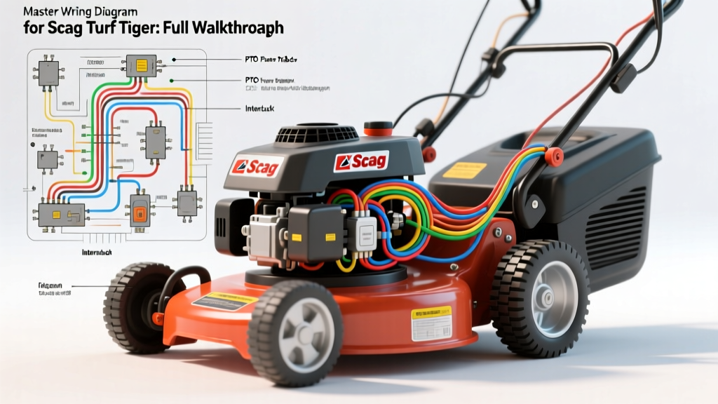
Introduction to the Scag Turf Tiger Electrical System
Navigating the wiring diagram for Scag Turf Tiger zero-turn mowers requires a solid understanding of both automotive-style 12V DC circuits and small engine magneto/charging systems. Whether your Turf Tiger is equipped with a Kawasaki FX series or a Kohler Command Pro engine, the chassis wiring harness relies on a complex safety interlock system, high-amperage PTO (Power Take-Off) circuits, and a solid-state Time Delay Module (TDM). In this complete walkthrough, we will dissect the primary circuits, decode the OEM wire color codes, and provide actionable troubleshooting data for commercial mower technicians.
Core Circuit Walkthrough: Reading the Wiring Diagram
1. Battery, Starter, and Charging Circuit (Heavy Gauge)
The foundation of the Turf Tiger electrical system begins at the 12V battery. Scag utilizes 6 AWG to 8 AWG stranded copper battery cables to handle the high cold-cranking amps (CCA) required by commercial V-twin engines. The positive battery cable routes directly to the starter solenoid's primary lug. A secondary 10 AWG red wire branches off this lug to supply constant 12V to the main harness fuse block and the ignition switch 'B' (Battery) terminal.
The charging system relies on a 3-phase stator located under the engine flywheel. Three 18 AWG Yellow wires carry raw alternating current (AC) from the stator to the voltage regulator/rectifier. The regulator converts this AC to a regulated 14.2V DC output, which is sent back to the battery via a 14 AWG Red wire. The regulator case must be grounded to the engine block; failure to maintain this ground path will result in an overcharge condition and battery boil-off.
2. Ignition and Engine Kill Circuit
The ignition switch acts as the central routing hub for the operator's commands. When tracing the wiring diagram for Scag Turf Tiger models, you will note a standard 5-pin or 6-pin automotive switch. Turning the key to the 'Run' position sends 12V through a 14 AWG White wire to the engine ignition module and the Time Delay Module (TDM). Crucially, the engine kill circuit does not cut fuel; it grounds the ignition coils. A 14 AWG Black/White tracer wire routes from the ignition switch 'G' (Ground) terminal to the engine's magneto kill terminals. When the key is turned off, this wire completes the ground circuit, collapsing the magnetic field in the coils and stopping the spark.
3. PTO Clutch and Safety Interlock System
The PTO clutch is the most electrically demanding component on the mower, typically drawing between 3.5 and 5.0 amps. Because it is a heavy inductive load, engaging and disengaging the clutch creates massive voltage spikes. Scag integrates an arc suppression diode or a dedicated relay to protect the dashboard PTO switch. The PTO switch sends a 12V signal via a 12 AWG Green wire to the PTO relay coil.
The safety interlock system monitors the seat switch, lap bar (neutral) switches, and PTO switch. These low-amperage sensor circuits utilize 16 AWG to 18 AWG wires (typically Gray, Orange, and Blue) that feed into the interlock control module or a series of 5-pin ISO mini-relays. If the operator stands up while the PTO is engaged, the normally-closed seat switch opens, triggering the Time Delay Module (TDM) to interrupt the PTO relay ground after a 1.5-second delay, safely shutting off the blades without stalling the engine immediately.
Scag Turf Tiger Wire Color Code Reference Chart
Use this reference chart when performing continuity tests or splicing damaged harnesses. Always verify with your specific model year's schematic, as OEM suppliers occasionally substitute colors.
| Wire Color | AWG Size | Circuit Function | Connector Type |
|---|---|---|---|
| Red | 6, 10, 14 | Battery Positive, Constant 12V, Regulator DC Out | Ring Terminal, AMP Mate-N-Lok |
| Black | 6, 10, 14 | Main Ground, Engine Block Ground, Coil Kill | Ring Terminal, Spade |
| Purple | 14 | Starter Solenoid Trigger (S Terminal) | Weather-Pack, Spade |
| White | 14 | Ignition 'Run' 12V, TDM Power Input | AMP Superseal |
| Green | 12 | PTO Clutch 12V Positive Feed | Weather-Pack (2-pin) |
| Yellow | 18 | Stator AC Output (3-phase) | Molex MX150, Spade |
| Gray | 16 | Safety Interlock Sensor Signals | AMP Superseal |
Ignition Switch Pinout Configuration
When diagnosing a no-crank or no-spark condition, testing the ignition switch is critical. Below is the standard pinout for the Scag Turf Tiger 5-position ignition switch.
| Terminal | Label | Function | Continuity State |
|---|---|---|---|
| B | Battery | Constant 12V Input | Always Hot |
| S | Start | Solenoid Trigger | Hot ONLY in 'Start' |
| I | Ignition | Run Circuit Power | Hot in 'Run' and 'Start' |
| G | Ground | Magneto Kill Circuit | Grounded ONLY in 'Off' |
| L | Lights | Accessory / Headlights | Hot in 'Run' (or dedicated toggle) |
Common Electrical Failure Modes & Troubleshooting
Commercial mowers operate in harsh environments characterized by extreme vibration, moisture, and debris. Here are the most frequent failure modes found when tracing the wiring diagram for Scag Turf Tiger units, along with diagnostic steps.
Decision Tree: PTO Clutch Will Not Engage
- Step 1: Check the PTO Fuse. Locate the 10A or 15A inline fuse on the main harness. If blown, inspect the 12 AWG Green wire for chafing against the chassis or engine tin.
- Step 2: Verify Voltage at the Clutch. With the engine running and PTO switch pulled, use a multimeter to test for 12V at the clutch connector.
- If 12V is present but clutch doesn't engage: The electrical system is fine. Check the mechanical air gap. Use a feeler gauge to verify the clutch rotor-to-armature gap is between 0.012' and 0.018'. Adjust the three set screws if necessary.
- If 0V is present: Proceed to Step 3.
- Step 3: Test the Interlock Relays. The PTO circuit requires the lap bars to be in the neutral (outward) position and the operator to be in the seat. Bypass the seat switch temporarily by jumping the 16 AWG Gray wires at the connector. If the PTO engages, the seat switch plunger is misaligned or failed.
- Step 4: Inspect the Arc Suppression Diode. If the PTO switch keeps melting or the interlock relay fails repeatedly, the reverse-biased diode across the clutch terminals has likely shorted or opened. Replace it with a heavy-duty 1N5408 3A diode, ensuring the cathode stripe faces the 12V positive (Green) wire.
Decision Tree: Battery Not Charging (Stator/Regulator Fault)
- Step 1: AC Stator Test. Disconnect the 3-pin stator plug (Yellow wires). Set your multimeter to AC Voltage. Start the engine and run at 3600 RPM. You should read 28V to 35V AC between any two Yellow wires. If reading is below 20V AC, the stator is burnt out or the flywheel key has sheared, altering the magnetic timing.
- Step 2: Regulator DC Output Test. Reconnect the stator. Back-probe the regulator's DC output wire (Red). With the engine at 3600 RPM, you should read 13.8V to 14.4V DC. If AC input is good but DC output is below 12.6V, the internal rectifier bridge in the regulator has failed. Replace the regulator and apply dielectric grease to the AMP connector.
Authoritative Resources & Service Manuals
For model-specific schematics and torque specifications, always consult the original equipment manufacturer documentation. The following resources are essential for advanced electrical diagnostics on commercial turf equipment:
- Scag Power Equipment Official Service Manuals - Downloadable PDF wiring diagrams and parts breakdowns for all Turf Tiger generations.
- Kawasaki Motors Corp. FX Series Service Manual - Detailed stator, regulator, and ignition coil pinouts for the FX801V and FX850V engines commonly paired with Scag chassis.
- SAE J1128: Low Tension Primary Cable Standard - The Society of Automotive Engineers standard defining the temperature and abrasion resistance requirements for the 18 AWG to 6 AWG wires used in heavy-duty mower harnesses.