Decoding Automotive Wiring Diagram Colours: A Beginner's Foundation
When you first open a factory service manual or an aftermarket repair guide, the sheer volume of wiring diagram colours and alphanumeric codes can feel like reading an alien language. Unlike residential electrical work, where black is universally "hot" and white is "neutral," automotive electrical systems rely on a complex matrix of base colors, tracer stripes, and circuit identification numbers. Understanding these wiring diagram colours is the single most critical fundamental skill for any aspiring automotive diagnostician.
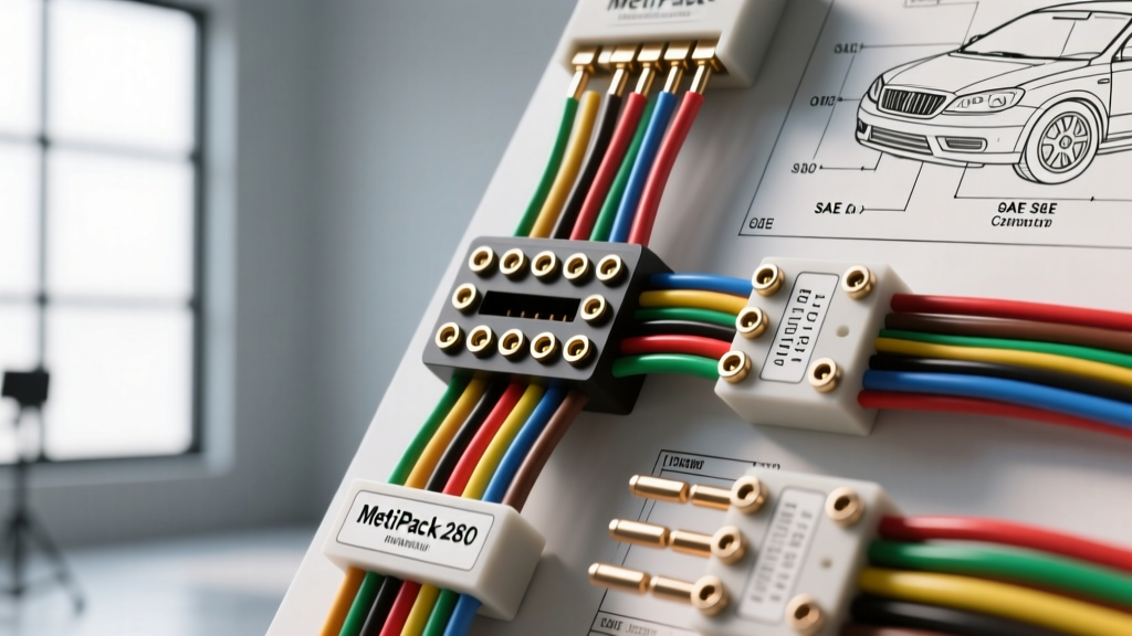
This beginner-friendly guide breaks down the standardized color codes established by the Society of Automotive Engineers (SAE), explains how major OEMs like Ford and GM apply them, and provides actionable troubleshooting steps for real-world scenarios involving common connectors like the Delphi/Aptiv Metri-Pack 280 series.
The Anatomy of an Automotive Wire Color Code
Automotive wires are rarely a single solid color. To accommodate the thousands of circuits in a modern vehicle, manufacturers use a base color with a secondary "tracer" or "stripe" color. In wiring schematics, this is represented by a two-letter or three-letter abbreviation.
For example, a wire labeled BK/WT on a diagram indicates a Black base wire with a White tracer stripe. According to SAE J1128 standards, the tracer stripe typically covers between 15% and 30% of the wire's circumference and runs longitudinally down the jacket. The first abbreviation always denotes the base color, while the second denotes the tracer.
Standard SAE Color Abbreviations Chart
Memorizing these abbreviations is mandatory for reading OEM wiring diagram colours efficiently. Below is the standard reference chart used across most North American and international service manuals.
| Abbreviation | Color | Abbreviation | Color |
|---|---|---|---|
| BK | Black | OG (or OR) | Orange |
| BL | Blue | PK | Pink |
| BR (or BN) | Brown | RD | Red |
| DG (or DB) | Dark Green | TN (or TA) | Tan |
| GN (or GR) | Green | VT (or VI) | Violet |
| GY | Gray | WT | White |
| LB (or SB) | Light Blue | YL | Yellow |
OEM Variations: Ford vs. GM vs. Chrysler
While the physical wiring diagram colours adhere to SAE standards, the way manufacturers label them on the schematic varies wildly. Recognizing these differences is key to tracing circuits accurately.
Ford Motor Company
Ford wiring diagrams are highly visual and rely heavily on circuit numbers and color codes. A typical Ford wire label on a schematic looks like 15S-PK/LB. In this example, "15S" is the circuit identification number, and "PK/LB" denotes the wiring diagram colours (Pink base with Light Blue tracer). Ford also uses specific color conventions for power distribution: Red (RD) is almost exclusively used for unswitched battery positive (B+), while Black (BK) is reserved for chassis grounds.
General Motors (GM)
GM service information takes a slightly different approach. While they still utilize wiring diagram colours (e.g., DK GRN/WHT for Dark Green with White tracer), GM places a heavier emphasis on the Circuit ID (CKT). In many modern GM diagrams, the physical color is secondary to the CKT number (e.g., CKT 1234). When tracing a GM harness, you must often look at the connector end-view (cavity pinout) rather than relying solely on the wire color, as GM frequently reuses color combinations across different modules.
Wire Gauge (AWG) and Connector Context
Color codes do not exist in a vacuum; they are tied to specific wire gauges and connector cavities. When working with ubiquitous connectors like the Metri-Pack 280 series, understanding the relationship between the wire size and its function is crucial.
- 18 AWG (0.80 mm²): Standard for low-current sensor signals (e.g., MAP sensors, TPS). Typically features thin tracer stripes.
- 14 AWG (2.0 mm²): Used for medium-current loads like fuel injectors or ignition coils. Often solid colors or wide tracers.
- 10 AWG (5.0 mm²) and larger: Reserved for high-current power feeds (e.g., starter solenoids, main PCM relays). Usually solid Red, Orange, or Black.
When probing a Metri-Pack 280 connector, always verify the cavity number stamped on the plastic housing rather than just matching the wire color. Aftermarket repairs or previous technician errors often result in mismatched colors in specific cavities.
Decoding CAN Bus Wiring Diagram Colours
Modern vehicles rely on Controller Area Network (CAN) bus systems for module-to-module communication. These are high-speed, low-voltage digital signals transmitted over twisted-pair wiring. Identifying CAN bus wiring diagram colours is a frequent requirement for beginners diagnosing communication faults (U-codes).
Standard OBD-II DLC CAN Bus Pinout
At the Data Link Connector (DLC), typically located under the driver's side dash, the CAN bus pins are standardized globally by ISO 15765-4. However, the physical wire colors leading to the DLC can vary. Below is a common reference for modern vehicles:
| DLC Pin | Function | Common Wiring Diagram Colours |
|---|---|---|
| Pin 6 | CAN High (Bus +) | Green (GN), Yellow (YL), or White (WT) |
| Pin 14 | CAN Low (Bus -) | Blue (BL), Green/Black (GN/BK), or Gray (GY) |
| Pin 4 & 5 | Signal / Chassis Ground | Black (BK) or Brown (BR) |
| Pin 16 | Battery Positive (B+) | Red (RD) or Orange (OG) - 14 AWG |
Pro Tip: CAN High and CAN Low wires are always twisted together (typically 3 to 4 twists per inch) to cancel out electromagnetic interference (EMI). If you untwist them during a repair, you will induce signal noise and trigger network communication codes.
Real-World Troubleshooting: When Colours Lie
As outlined in foundational electrical texts like those provided by AutoShop 101, a multimeter is your ultimate source of truth. Physical wire colors in the engine bay frequently degrade or are altered, leading beginners astray if they rely solely on the schematic.
The UV Degradation Factor
Under-hood harnesses are subjected to extreme heat and ultraviolet (UV) radiation. Over a vehicle's lifespan, certain wiring diagram colours undergo severe visual shifts:
- Red (RD) fades to a pale pink or even off-white.
- Black (BK) oxidizes and turns a chalky, light gray.
- Dark Green (DG) often fades to a pale yellow or brown.
If you are looking for a BK/WT ground wire in a 10-year-old engine bay, you may actually be looking at a faded gray wire with a barely visible dirty white stripe. Always use a digital multimeter (DMM) to perform a voltage drop test to the battery negative terminal to verify a ground circuit, rather than trusting your eyes.
Identifying "The Hack"
Previous owners or inexperienced mechanics often perform "backyard splices" using whatever scrap wire they have in their garage. If your wiring diagram calls for a 16 AWG Yellow/Light Green (YL/LB) wire at cavity 4 of the PCM connector, but you physically see a solid blue 18 AWG wire spliced into the harness with a crimp connector, you have found an aftermarket hack. In these cases, trace the circuit backward from the component, or forward from the module, using a tone generator or DMM continuity test to map the actual path.
Summary for Beginners
Mastering wiring diagram colours is about understanding the system, not just memorizing a rainbow. Start by learning the SAE abbreviations. Next, familiarize yourself with your specific vehicle's OEM labeling quirks (like Ford's circuit numbers or GM's CKT IDs). Finally, always cross-reference the physical wire color with the connector cavity pinout and verify the circuit's electrical integrity with a multimeter. For further reading on OEM specific repair procedures and connector end-views, resources like the Motorcraft Service Information portal provide invaluable factory-level schematics to practice your decoding skills.