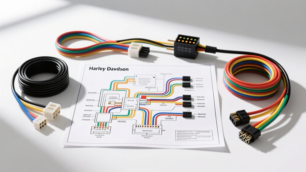
Introduction to Harley-Davidson Electrical Architecture
Deciphering a wiring diagram for Harley Davidson motorcycles requires a fundamental understanding of their unique electrical evolution. From the legacy of the Evolution (Evo) engines to the complex, CAN bus-driven Milwaukee-Eight (M8) platforms, Harley-Davidson has continually refined its electrical topology. Unlike many Japanese or European manufacturers that rely heavily on multiplexed data streams for basic functions, Harley-Davidson maintains a robust, hardwired approach for critical safety and ignition circuits, blending analog reliability with modern digital engine management.
Whether you are tracing a parasitic draw on a 2008 Twin Cam Dyna or diagnosing a CAN bus fault on a 2021 Road Glide, the factory service manual (FSM) schematic is your primary map. This complete walkthrough breaks down the core circuits, color codes, and connector pinouts necessary to navigate the electrical nervous system of America's iconic V-Twin.
How to Read a Wiring Diagram for Harley Davidson Motorcycles
Harley-Davidson schematics utilize a standardized grid and node system. Power distribution typically originates from the main circuit breaker (often rated at 30A or 40A) located directly at the starter solenoid battery terminal. From there, unswitched battery positive (Red) feeds the ignition switch and voltage regulator.
Color Code Standards and Nomenclature
Harley-Davidson uses a distinct two-letter abbreviation system for wire colors, which is critical when cross-referencing your physical harness with the wiring diagram for Harley Davidson models. A wire labeled R/W is a Red wire with a White tracer. Understanding these codes prevents catastrophic miswiring, especially around the Delphi or Bosch Engine Control Modules (ECM).
| Abbreviation | Color | Typical Circuit Function | Common AWG Size |
|---|---|---|---|
| BK | Black | Chassis Ground / Return Path | 18 AWG - 4 AWG |
| R | Red | Unswitched Battery Positive (Hot at all times) | 14 AWG - 2 AWG |
| O | Orange | Switched Ignition Positive (Hot in Run/Start) | 14 AWG - 18 AWG |
| W | White | CAN High / Data Bus / Sensor Signals | 20 AWG |
| Y | Yellow | Stator AC Output (3-Phase) | 10 AWG (High Temp) |
| G | Green | Left Turn Signal / Instrumentation | 18 AWG |
| V | Violet | Right Turn Signal / Fuel Pump Feed | 18 AWG |
| BN | Brown | Tail Light / Running Lights | 18 AWG |
Core Circuit Walkthrough: Ignition and Starter Relay
The starter circuit on a fuel-injected Harley-Davidson is a masterclass in safety interlocks. When reviewing the wiring diagram for Harley Davidson EFI models, you will notice the starter relay coil (Pins 85 and 86) is not grounded directly to the frame. Instead, the ground path is controlled by the ECM, which requires validation from three critical switches: the Bank Angle Sensor (BAS), the clutch interlock switch, and the neutral indicator switch.
Starter Relay Pin Configuration
Harley-Davidson typically uses a standard ISO mini relay for the starter solenoid engagement. Understanding the pinout is vital for bench-testing:
- Pin 30: Constant 12V from the main circuit breaker (Usually 10 AWG Red wire).
- Pin 87: Output to the starter solenoid 'S' terminal (Usually 10 AWG Green/White or Gray wire).
- Pin 86: Switched 12V from the ignition switch via the start button (Orange/White tracer).
- Pin 85: ECM-controlled ground. The ECM completes this circuit only if the BAS is upright and the clutch/neutral parameters are met.
Pro-Tip: If the starter solenoid clicks but the engine does not crank, perform a voltage drop test across Pin 30 and Pin 87 while the button is depressed. A reading above 0.5V indicates pitted internal relay contacts, requiring immediate replacement to prevent a stranded motorcycle.
Charging System: Stator and Regulator/Rectifier Topology
The charging system is a frequent point of failure on touring models due to heat soak and high electrical loads from accessories. The stator generates 3-phase AC voltage, which is routed via three Yellow (Y) wires to the Regulator/Rectifier (R/R). According to Electrosport Technical Resources, testing the stator requires verifying both continuity and isolation.
Stator Diagnostic Specifications
- Continuity Test: Set your multimeter to Ohms. Measure across the three Yellow stator pins in the harness connector. You should read between 0.2 and 0.8 ohms. An open circuit (OL) indicates a broken internal winding.
- Ground Isolation Test: Set your meter to the highest Mega-ohm range. Place one probe on a stator Yellow wire and the other on a clean engine case ground. The reading must be infinite (OL). Any continuity here means the stator epoxy has failed, allowing AC voltage to short to the engine block, which will destroy the R/R and potentially the ECM.
- AC Output Test: With the engine running at 3,000 RPM, measure AC voltage between the Yellow pins. You should see 40V to 70V AC per phase.
The DC output side of the R/R utilizes heavy-gauge wiring to handle up to 45 amps of charging current. The positive output is typically a 10 AWG or 8 AWG Red wire, while the negative is a 10 AWG Black wire. These must be terminated with high-strand-count marine-grade lugs and sealed with adhesive-lined heat shrink to prevent moisture-induced galvanic corrosion.
ECM Pinouts and the CAN Bus Network
Modern Harley-Davidson motorcycles utilize a Controller Area Network (CAN bus) to allow the ECM, ABS module, and Instrument Cluster to communicate. On the wiring diagram for Harley Davidson M8 models, the CAN bus is represented as a twisted pair of wires: CAN High (typically White/Green) and CAN Low (typically White/Blue).
These wires operate at high frequencies and are highly susceptible to electromagnetic interference (EMI). When repairing a broken CAN bus wire, you must maintain the twist rate (at least one twist per inch) and use solder-seal splices rather than standard crimp connectors. The termination resistance of the CAN bus should measure exactly 60 ohms across the High and Low lines with the battery disconnected, indicating that both the ECM and ABS module termination resistors are intact.
Delphi MT4 ECM Common Pin Reference (Twin Cam Era)
| Pin Number | Wire Color | Circuit Description |
|---|---|---|
| 1 | BK | ECM Main Ground (Must be clean bare metal) |
| 2 | R/W | Switched 12V Ignition Feed |
| 18 | GY | Vehicle Speed Sensor (VSS) Signal |
| 32 | O/W | Front Injector Driver (Low Side) |
| 34 | BN/W | Rear Injector Driver (Low Side) |
Real-World Troubleshooting: The Infamous Ground Issue
If there is one universal truth in Harley-Davidson electrical diagnostics, it is that 80% of unexplained electrical gremlins stem from poor grounding. Harley-Davidson frames are heavily powder-coated and painted. The factory uses star washers to bite through this finish, but vibration and thermal cycling often cause these connections to degrade.
When utilizing a wiring diagram for Harley Davidson troubleshooting, always locate the designated Ground Splice Packs (SP) and Ground Points (G). For example, the main engine ground strap connects the transmission case to the frame. If this strap corrodes, the starter motor will attempt to ground through the throttle cable, clutch cable, or speedometer sensor, melting them instantly.
Always perform a millivolt drop test under load. Place your multimeter leads across the suspected ground connection while the circuit is active. A reading greater than 0.1V (100mV) on a ground circuit indicates excessive resistance. Clean the contact area down to bare metal using a brass wire brush, apply a thin layer of dielectric grease to the edges to prevent oxidation, and secure it with a fresh stainless steel star washer and torque to factory specifications.
Authoritative Resources and Schematics
While aftermarket guides provide excellent overviews, working on modern fuel-injected motorcycles requires precision. Always cross-reference your physical harness with the official Harley-Davidson Service Portal documentation for your specific VIN. Furthermore, ensure all replacement wiring and connectors meet or exceed SAE J1128 standards for low-tension primary cables, ensuring the insulation can withstand the extreme heat generated by the rear cylinder exhaust header.
By mastering the color codes, understanding the safety interlocks, and respecting the high-current demands of the charging system, you can confidently diagnose, repair, and upgrade the electrical system of any Harley-Davidson motorcycle.