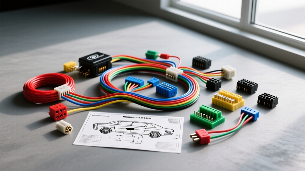
Core Architecture of the 1965 Mustang Electrical System
The 1965 Ford Mustang represents a pivotal transition year in American automotive electrical engineering. For restorers and custom builders, navigating a 65 Mustang wiring diagram requires an understanding of the vehicle's split-year production architecture. Early production models (often colloquially referred to as 1964.5 or early 65) utilized a DC generator paired with a mechanical voltage regulator. However, mid-to-late 1965 Mustangs transitioned to the Autolite 1G alternator. This distinction drastically alters the main under-hood harness routing and the regulator pinouts you must reference during a restoration.
The Generator to Alternator Transition
When working with a late-build 1965 Mustang equipped with the Autolite 1G alternator, the system relies on a specific three-wire configuration to manage field excitation and battery charging. Unlike modern single-wire internally regulated alternators, the 1G requires external regulation via the fender-mounted mechanical regulator.
- BAT Terminal: Yellow with Black hash (10 AWG). Routes directly to the battery side of the ammeter shunt.
- STA (Stator) Terminal: White with Black hash (14 AWG). Provides an AC tap signal to the regulator to confirm the alternator is spinning and generating power.
- FLD (Field) Terminal: Green with Red stripe (14 AWG). Supplies the pulsed DC ground path from the regulator to the alternator's rotor windings to control magnetic field strength.
According to the SAE J1128 Low Tension Primary Cable Standard, maintaining the correct AWG and insulation type for these specific runs is critical to prevent voltage drop, which can cause the mechanical regulator to overcharge the battery in an attempt to compensate for harness resistance.
The Ammeter Shunt: Physics and Failure Modes
Unlike the 1966 and later models that relied on a simple alternator warning lamp (commonly known as an idiot light), the 1965 Mustang features an in-dash ammeter. However, this is not a traditional series-wound ammeter where all alternator output flows directly through the gauge's internal shunt. Instead, the 1965 ammeter operates as a highly sensitive millivolt meter measuring the voltage drop across a calibrated shunt wire integrated directly into the main under-hood harness.
This design is a frequent point of failure during amateur restorations. If you are replacing the main harness, you must ensure the replacement uses the exact factory-calibrated shunt wire. Substituting this specific segment with standard 10 AWG copper wire will alter the resistance profile of the circuit. Because the ammeter is reading millivolts across this specific resistance, a generic wire swap will render the ammeter readings entirely inaccurate, often showing a perpetual discharge even when the alternator is functioning perfectly.
Advanced Troubleshooting: To verify the health of the ammeter circuit, perform a voltage drop test across the main harness feed with the engine running at 2,000 RPM and the high-beam headlights engaged. A healthy factory shunt will show a millivolt drop proportional to the gauge deflection. If the gauge reads zero but you measure significant voltage drop at the battery terminals, the ammeter's internal movement or the twin 16 AWG sense wires (Green with Red stripe) routed through the firewall are compromised.
Under-Dash Harness and Ignition Switch Matrix
The under-dash harness routes through the firewall via a multi-pin molded rubber connector, terminating at the 4-position rotary ignition switch. This switch acts as the primary distribution node for the vehicle's accessory and ignition circuits. Understanding the terminal mapping is essential for diagnosing parasitic draws or accessory back-feed issues.
| Terminal | Function | Wire Color | AWG | Active Positions |
|---|---|---|---|---|
| BAT | Main Battery Feed | Red w/ Blue hash | 12 AWG | Constant (Hot at all times) |
| ACC | Accessory Feed (Radio, Wipers) | Black w/ Yellow hash | 14 AWG | ACC, ON |
| IGN | Ignition Coil & Gauges | Red w/ Green hash | 12 AWG | ON, ST (Bypasses resistor wire) |
| ST | Starter Solenoid Trigger | Brown | 14 AWG | ST (Spring return to ON) |
Reference: Detailed factory schematic overlays can be cross-referenced via the Average Joe Restoration Wiring Archives for exact firewall bulkhead pin assignments.
Instrument Cluster: The King Seeley Thermal Gauges
The 1965 Mustang instrument cluster relies on the King Seeley thermal gauge system. Unlike modern electromagnetic or stepper-motor gauges, these utilize a bimetallic strip heated by a pulse-width modulated signal. The cluster receives 14.4V from the ignition switch, which is stepped down by the Instrument Cluster Voltage Regulator (ICVR) to a pulsing 5V average.
The gauge senders located on the engine block and fuel tank are variable resistors tied to chassis ground. As engine temperature or fuel level changes, the sender's resistance shifts, altering the current flow through the gauge's heating element, which physically bends the needle. The factory resistance specification for the fuel, oil pressure, and temperature senders is strictly 10 ohms to 73 ohms.
| Gauge | Sender Wire Color | Resistance (Full/Hot) | Resistance (Empty/Cold) |
|---|---|---|---|
| Fuel Level | Yellow / White (16 AWG) | 10 Ohms | 73 Ohms |
| Coolant Temp | Red / White (16 AWG) | 10 Ohms | 73 Ohms |
| Oil Pressure | White / Red (16 AWG) | 10 Ohms | 73 Ohms |
Diagnostic Tip: If all three gauges peg to the maximum reading simultaneously, the ICVR has failed in the closed position, sending full 14.4V to the 5V-rated heating elements. Immediately cut ignition power to prevent melting the gauge pod and destroying the sender units. Consult the Haynes Ford Mustang Repair Manual for ICVR bench-testing procedures.
Headlight and Floor Dimmer Circuit Analysis
The headlight circuit in the 65 Mustang is protected by an internal thermal circuit breaker housed within the headlight switch itself, rather than a standard glass fuse in the fuse block. Power flows from the battery junction block via a 14 AWG Black/Orange wire to the headlight switch, then out to the floor-mounted dimmer switch.
Floor Dimmer Switch Pinout
- Power In: Red/Yellow (14 AWG)
- Low Beam Out: Tan/White (14 AWG)
- High Beam Out: Green/Black (14 AWG)
Real-World Failure Mode: The floor dimmer switch is highly susceptible to moisture, road salt, and debris intrusion. Corrosion on the brass spade terminals introduces severe high resistance, causing a massive voltage drop before the power ever reaches the headlamps. This results in dim, yellowish headlights even with new bulbs and alternators.
The Modern Fix: Advanced restorers bypass the floor switch entirely. By relocating the dimmer function to the turn signal stalk and utilizing two 40A Bosch-style relays with 10 AWG direct feeds from the battery junction block, you eliminate 40 feet of undersized 14 AWG factory wiring. This upgrade is mandatory if you are installing high-draw H4 halogen bulbs or modern LED headlamp assemblies to ensure optimal lumen output and prevent the factory headlight switch thermal breaker from tripping.
Turn Signal Flasher and LED Upgrades
The factory thermal flasher relay (C9UZ-13350-A) relies on a bimetallic strip that heats and bends to break the circuit, creating the familiar clicking sound. When upgrading to modern LED taillights, the drastically reduced current draw (often under 0.5A total) prevents the bimetallic strip from heating. This results in a solid light with no flashing.
To resolve this without splicing in ugly, heat-generating 6-ohm 50W load resistors behind the tail lamps, replace the thermal can under the dash with a solid-state electronic flasher (e.g., Tridon EL12 or equivalent). Ensure the electronic flasher is wired in parallel with the factory harness and features a dedicated ground wire, as the original thermal flasher relied on the metal can body grounding through the dash bracket.