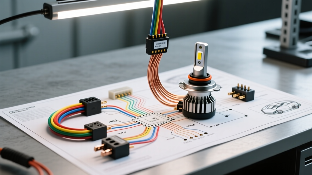
Introduction to LED Headlight Circuit Architecture
Upgrading from OEM halogen or HID assemblies to high-output LED arrays requires more than simply swapping bulbs. Modern LED headlight systems draw current differently, possess distinct inrush characteristics, and frequently trigger Body Control Module (BCM) faults due to Pulse Width Modulation (PWM) monitoring. This comprehensive walkthrough dissects the universal LED headlight wiring diagram, focusing on heavy-duty relay harness integration, precise AWG specifications, waterproof connector standards, and PWM decoding protocols. Whether you are retrofitting a 2015 Jeep Wrangler JK or a 2020 Toyota Tacoma, understanding the underlying circuit architecture is critical to preventing voltage drop, flickering, and premature driver failure.
Anatomy of a Universal LED Headlight Wiring Diagram
A properly engineered LED headlight wiring diagram isolates the high-current draw of the LED drivers from the vehicle's delicate OEM headlight switch and factory wiring. Factory headlight circuits are often designed with marginal wire gauges (typically 18 AWG or 16 AWG) intended for 55W halogen bulbs. Running high-performance LED drivers (which can pull 3.5A to 5A continuous per side) directly through OEM wiring can lead to excessive voltage drop and melted connectors. The solution is a dedicated relay harness that pulls power directly from the battery, using the OEM headlight plug solely as a low-current trigger signal.
The ISO Mini Relay: Pinout and Wire Color Codes
The core of the wiring diagram is the Bosch-style ISO mini relay. This electromechanical switch handles the heavy lifting. Below is the standard pinout configuration utilized in premium automotive lighting harnesses, aligned with standard aftermarket color codes:
| Relay Pin | Function | Wire Color | AWG Size | Connection Point |
|---|---|---|---|---|
| Pin 30 | Common (12V+ Power In) | Red | 10 AWG | Positive Battery Terminal (via inline 15A ATO fuse) |
| Pin 87 | Normally Open (12V+ Out) | Red | 10 AWG | LED Driver Positive Input |
| Pin 86 | Coil Trigger (12V+ Signal) | Yellow or White | 18 AWG | OEM Headlight Harness Positive Wire |
| Pin 85 | Coil Ground | Black | 18 AWG | Chassis Ground or Negative Battery Terminal |
Note: Always verify relay pinouts with a multimeter. Some imported relays swap Pin 86 and Pin 85, which can cause issues if the relay contains an internal flyback diode.
Wire Gauge (AWG) Selection and Voltage Drop Calculations
Selecting the correct American Wire Gauge (AWG) is non-negotiable in automotive lighting. According to Daniel Stern's authoritative relay wiring guide, voltage drop is the primary enemy of headlight performance. While LEDs are more efficient than halogens, high-lumen aftermarket LED arrays often require 45W to 65W per bulb, equating to roughly 3.75A to 5.4A of continuous draw.
- 10 AWG Wire (Main Power/Ground): Capable of handling 30A safely. Used for Pin 30 and Pin 87 to ensure the voltage drop over a 6-foot harness run remains below 0.1V. This guarantees the LED driver receives a full 13.8V - 14.4V from the alternator, maximizing lumen output and thermal efficiency.
- 18 AWG Wire (Trigger/Ground): Capable of handling 5A. Used for Pin 86 and Pin 85. The relay coil draws less than 150mA, making 18 AWG more than sufficient while remaining flexible enough to route through the firewall or behind the grille.
Step-by-Step Wiring Walkthrough
- Battery and Ground Preparation: Disconnect the negative battery terminal. Route the 10 AWG red power wire from the positive battery terminal, ensuring it avoids hot exhaust components and sharp chassis edges. Install an inline 15A ATO fuse within 6 inches of the battery post. Terminate the wire with a copper ring terminal, crimped using a Mil-Spec hex crimp tool, and coated in dielectric grease to prevent galvanic corrosion.
- Relay Mounting: Mount the ISO relay in the engine bay, preferably on the passenger side inner fender well. Ensure the relay socket faces downward to prevent water intrusion into the terminal cavities.
- Trigger Wire Integration: Unplug the OEM headlight connector (e.g., H11, H7, or 9005). Use a Posi-Tap or a dedicated OEM-matched pigtail adapter to connect the 18 AWG yellow trigger wire to the OEM positive low-beam wire. Never use cheap scotch-locks, which slice through the wire strand and invite moisture wicking.
- LED Driver Connection: Connect the 10 AWG output (Pin 87) and the main harness ground to the LED driver. For professional installations, cut off the standard PVC connectors and solder/splice the wires into TE Connectivity DEUTSCH DT series waterproof connectors.
- System Testing: Reconnect the battery. Turn on the headlights. You should hear an audible 'click' from the relay. Measure voltage at the LED driver input with a digital multimeter; it should read within 0.2V of the battery's resting voltage.
CANbus Integration and PWM Signal Decoding
Modern vehicles (2014+ Chrysler/Jeep, Ford, VW/Audi, and GM) utilize a Body Control Module (BCM) to monitor headlight circuit health. Instead of sending a constant 12V signal, the BCM uses Pulse Width Modulation (PWM)—rapidly pulsing the voltage on and off—to check for open circuits or short circuits. Furthermore, many vehicles multiplex the headlight trigger wire over a CAN-bus network.
Because LED drivers do not exhibit the same thermal resistance curve as a halogen filament, the BCM interprets the low initial current draw as a 'blown bulb' and cuts power entirely, resulting in severe flickering or complete shutoff. To resolve this, the wiring diagram must incorporate an inline PWM decoder or anti-flicker capacitor bank between the OEM trigger wire and Pin 86 of the relay. These decoders absorb the rapid voltage spikes and release a smooth, continuous 12V signal to the relay coil, tricking the BCM into registering a healthy halogen load.
Connector Selection: DEUTSCH DT vs. Standard PVC
Standard PVC bullet connectors and H4 plastic adapters are highly susceptible to moisture intrusion, leading to terminal oxidation and high-resistance faults. For permanent LED headlight wiring diagrams, upgrade all under-hood connections to IP67-rated or IP69K-rated connectors. The TE Connectivity DEUTSCH DT series utilizes solid copper contacts with silicone rear wire seals and a thermoplastic wedgelock mechanism. When crimping DEUTSCH contacts, always use the correct cavity depth and ensure the wire insulation seal is visible past the contact barrel to guarantee a watertight barrier.
Troubleshooting Matrix: Real-World Failure Modes
Even with a flawless wiring diagram, environmental factors and vehicle-specific quirks can cause issues. Use the following diagnostic matrix to troubleshoot common LED headlight wiring failures:
| Symptom | Root Cause | Diagnostic Step | Corrective Action |
|---|---|---|---|
| Headlights flicker rapidly upon startup | PWM signal from BCM confusing the LED driver | Probe trigger wire with oscilloscope or multimeter (min/max mode) | Install inline PWM anti-flicker decoder module |
| Dash 'Bulb Out' warning illuminated | BCM detects low resistance (LED draws less current than halogen) | Scan BCM for lighting circuit fault codes | Wire 6-ohm 50W load resistor in parallel with the trigger circuit |
| One headlight noticeably dimmer than the other | Severe voltage drop on the passenger side ground wire | Perform voltage drop test across the ground wire under load | Clean chassis ground point, apply conductive grease, upgrade to 8 AWG ground |
| AM/FM radio static when headlights are on | Electromagnetic Interference (EMI) from unshielded LED driver | Verify driver compliance with SAE J1113 EMC standards | Snap ferrite core chokes onto the driver output wires; relocate driver away from antenna |
| Relay clicks rapidly but lights do not turn on | Insufficient current on trigger wire to hold relay coil closed | Measure voltage at Pin 86 and Pin 85 while headlights are on | Check for corroded trigger tap; upgrade trigger ground to direct battery negative |
Conclusion
Executing a proper LED headlight wiring diagram requires a methodical approach to current capacity, voltage preservation, and module communication. By utilizing a heavy-duty 10 AWG relay harness, implementing proper Mil-Spec crimping techniques, and integrating CANbus/PWM decoders where necessary, you ensure your LED lighting system operates reliably, safely, and at maximum optical efficiency for the life of the vehicle.