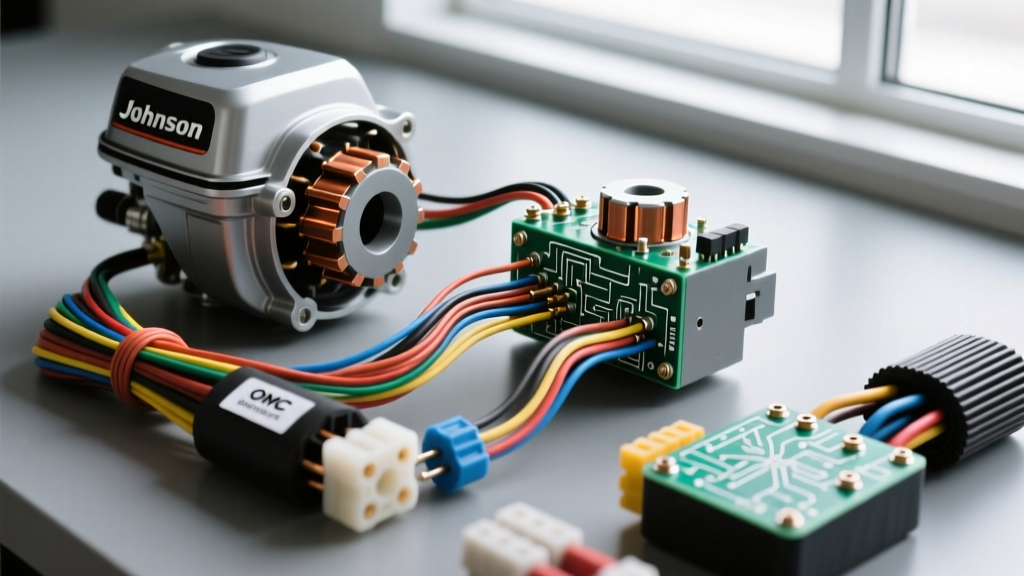
Decoding the 2 Stroke Johnson Outboard Wiring Diagram PDF
When diagnosing electrical faults in classic Outboard Marine Corporation (OMC) engines, securing an accurate 2 stroke Johnson outboard wiring diagram PDF is only the first step. Unlike standard automotive 12V DC systems, Johnson and Evinrude 2-stroke outboards utilize a complex Capacitor Discharge (CD) ignition system. The stator generates high-voltage AC pulses that are rectified and stored in the powerpack (switchbox) before firing the ignition coils. Standard automotive diagnostic procedures will lead to false condemnations of expensive components. This advanced technical deep dive bridges the gap between the factory schematic and real-world bench testing.
OMC Stator and Powerpack Color Code Matrix
The foundation of any Johnson 2-stroke electrical diagnosis relies on understanding the OMC wire color standard. The table below maps the primary stator, trigger, and powerpack wires found in the wiring diagram.
| Component | Wire Color | Function | DVA Voltage Spec |
|---|---|---|---|
| Stator (Low Speed) | Blue / Blue-White | Charges powerpack at low RPM | > 180V DVA |
| Stator (High Speed) | Red / Red-White | Charges powerpack at high RPM | > 180V DVA (up to 400V) |
| Trigger Pack | White, Blue, Green (paired) | Signals SCR gate to fire coil | 0.6V - 1.2V DVA |
| Rectifier Input | Yellow / Yellow-Grey | AC input for battery charging | 28V - 40V AC (RMS) |
| Kill Circuit | Black-Yellow | Grounds primary to stop engine | Continuity to Ground (Off) |
The DVA Adaptor: Why Standard Multimeters Fail
A critical element missing from most basic interpretations of a 2 stroke Johnson outboard wiring diagram PDF is the testing methodology. OMC stators output sharp, high-frequency AC voltage spikes. A standard True-RMS digital multimeter (DMM) averages these spikes, often displaying readings 30% to 50% lower than the actual peak voltage. To properly test the circuit, you must use a Direct Voltage Adaptor (DVA), such as the Stevens SST-4512 or an equivalent peak-reading module.
Testing the High-Speed Stator Windings
Connect the DVA leads to the Red and Red-White stator wires. Crank the engine or run it at WOT (Wide Open Throttle). You should observe a minimum of 180V DVA, scaling up to 400V+ at higher RPMs. If the voltage drops out on one cylinder bank, the stator's internal high-speed winding is compromised, requiring a complete stator replacement. Ensure the stator ground ring is torqued to 40 in-lbs to prevent erratic grounding through the engine block.
Trigger Pack and Timer Base Diagnostics
The timer base (trigger) tells the powerpack exactly when to fire the SCR (Silicon Controlled Rectifier) gate. The wiring diagram will show three pairs of twisted wires: White/White-Black, Blue/Blue-Black, and Green/Green-Black. These connect to the timer base magnetic pickups.
- Resistance Check: Disconnect the main harness. Measure resistance between the paired wires. Expect 110-140 ohms depending on the exact year and model.
- DVA Output: Cranking the engine should yield 0.6V to 1.2V DVA on each trigger pair. A dead trigger will prevent the powerpack from discharging the capacitor to the ignition coil.
Rectifier and Voltage Regulator Diagnostics
The Johnson 2-stroke charging system utilizes a dedicated rectifier to convert the stator's AC output into DC current for battery charging. In the wiring diagram, the rectifier is easily identified by the Yellow and Yellow-Grey wires connecting directly from the stator to the rectifier assembly. The rectifier's center terminal (typically a Red wire) routes the rectified DC voltage to the starter solenoid's battery terminal.
Diode Testing Procedure
A failed rectifier will either result in a dead battery or allow reverse AC current to fry the powerpack. To test the rectifier, disconnect the Yellow stator wires and the Red output wire. Set your multimeter to the Diode Test setting.
- Place the positive lead on the Yellow wire terminal and the negative lead on the Red output terminal. You should read between 0.4V and 0.7V.
- Reverse the leads. The meter should read 'OL' (Open Loop), indicating the diode is blocking reverse current.
- Repeat this process for the Yellow-Grey wire terminal. If any diode reads 0.0V (shorted) or conducts in both directions, the rectifier must be replaced immediately to protect the CD ignition system.
Starter Solenoid and Choke Circuit Routing
While the CD ignition is high-voltage, the starting and choking circuits operate on standard 12V DC marine battery power. The main battery harness typically utilizes 4 AWG marine-grade tinned copper wire to handle the 150+ amp inrush current of the starter motor. The starter solenoid is triggered by a 12 AWG Yellow-Red wire from the ignition switch's 'Start' terminal.
The manual choke (primer) solenoid is wired via a Purple wire. When the ignition key is pushed in, the Purple wire receives 12V, grounding through the solenoid coil (approx. 4 ohms) to open the primer valve, enriching the cold-start mixture. A common failure point in the OMC wiring harness is corrosion inside the 14-pin Amphenol main connector. Always pack these connectors with marine-grade dielectric grease to prevent galvanic corrosion between the copper pins and brass sockets.
Kill Circuit Logic: Ground vs. Interrupt
In automotive applications, killing the ignition usually involves cutting power to the coil. In the Johnson 2-stroke wiring diagram, the kill circuit operates on a ground-to-kill logic. The Black-Yellow wire runs from the powerpack's primary ground terminal to the ignition switch. When the key is turned to 'Off', the switch connects the Black-Yellow wire to the engine block ground. This instantly bleeds the capacitor's stored energy to ground before it can reach the ignition coil, safely shutting down the engine. If an engine refuses to shut off via the key, immediately inspect the Black-Yellow wire for continuity breaks or a corroded ignition switch ground lug.
Advanced Troubleshooting: Intermittent Misfires at WOT
One of the most frustrating issues detailed in service forums regarding the 2 stroke Johnson outboard wiring diagram PDF is the high-RPM misfire. If the engine runs flawlessly at idle and mid-range but breaks up violently above 4500 RPM, the fault almost always lies in the high-speed stator winding or the powerpack's high-speed capacitor bank.
As engine RPM increases, the timer base advances the spark timing. The powerpack must discharge the capacitor faster and with higher energy to maintain the spark across the widening plug gap under extreme cylinder pressures. If the Red/Red-White high-speed stator wires are frayed inside the harness loom, or if the powerpack's internal SCR is heat-fatigued, the voltage will collapse under load. To isolate this, swap the powerpack's trigger wires between the misfiring cylinder and a known good cylinder. If the misfire moves, the timer base or trigger is at fault. If the misfire stays on the same cylinder, the powerpack or ignition coil is the culprit.
Authoritative References and Further Reading
For exact pinouts specific to your engine's serial number, always cross-reference your downloaded schematic with OEM service data. The following resources are industry standards for OMC marine electrical diagnostics:
- CDI Electronics Troubleshooting Guides - The premier manufacturer of aftermarket CD ignition components provides exhaustive DVA testing charts and stator resistance matrices for Johnson/Evinrude powerpacks.
- MarineEngine OMC Parts & Schematics Database - An essential repository for cross-referencing factory wiring diagrams with specific OEM part numbers and harness revisions.
- BoatUS Electrical Systems Archive - Excellent guidelines on marine-grade wire sizing (AWG), voltage drop calculations, and ABYC compliance for outboard battery harnesses.