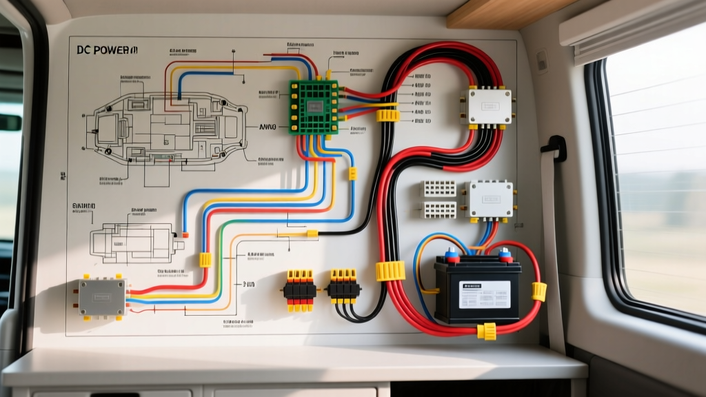
Understanding the Core Architecture of Van Electrical Systems
Transitioning from a standard vehicle owner to a DIY vanlifer requires a fundamental shift in how you view automotive electrical systems. A reliable self build campervan wiring diagram is not just a map of where cables go; it is a strict engineering blueprint that dictates the safety, efficiency, and longevity of your mobile home. Unlike standard automotive 12V systems that merely crank an engine and power basic ECU sensors, a campervan 'house' system must sustain high-draw continuous loads like 12V compressor refrigerators, induction cooktops (via inverters), and lithium battery management systems (BMS).
At its core, your DC wiring architecture consists of three distinct zones: the charging sources (alternator, solar panels, shore power), the energy storage (house battery bank), and the load distribution (DC fuse box and AC inverter). Bridging the gap between the vehicle's chassis electrical system and the house system is the most critical juncture in your build. Failing to isolate these systems properly can result in parasitic drains that strand you, or worse, alternator burnout due to unregulated lithium charging demands.
The Split-Charge Relay vs. DC-DC Charger Debate
Beginners often look at older campervan wiring diagrams and see a simple Voltage Sensitive Relay (VSR) or split-charge relay. While cheap and easy to wire, VSRs are fundamentally incompatible with modern lithium iron phosphate (LiFePO4) batteries and smart alternators. A smart alternator varies its output voltage (often dropping to 12.8V or lower to save fuel), which will prematurely disconnect a VSR or undercharge your house bank. Furthermore, lithium batteries have incredibly low internal resistance; a VSR will allow the alternator to push 100+ amps into a depleted battery, melting wiring and destroying the alternator's diode bridge.
Modern schematics mandate a DC-DC Battery Charger (e.g., Victron Orion or Renogy DCC50S). This device acts as an electronic gatekeeper, pulling a regulated, fixed amperage (typically 30A to 60A) from the alternator and applying the precise multi-stage charging profile required by your specific battery chemistry.
Decoding Vehicle Integration: Ford Transit CAP Pinout
When integrating your house diagram with the host vehicle, you must locate the OEM upfitter interfaces. For the ubiquitous Ford Transit (2015-2023), this is the Customer Access Point (CAP), located behind the driver's seat pedestal. Understanding the CAP pinout is crucial for triggering your DC-DC charger safely without splicing into critical OEM CAN bus wiring.
| CAP Pin Number | Wire Color (OEM) | Function | Max Load / Notes |
|---|---|---|---|
| Pin 1 (C1-1) | Red / Yellow Tracer | B+ (Battery Positive) | 30A - 60A (Check BCM fuse rating) |
| Pin 2 (C1-2) | Black | Chassis Ground | 30A - 60A Return path |
| Pin 3 (C1-3) | White / Blue Tracer | Ignition Sense (Run/Start) | 5A Max - Use to trigger DC-DC relay |
| Pin 4 (C1-4) | Yellow / Green Tracer | Accessory Delay | 5A Max - Active after key off |
Expert Tip: Never pull high-amp DC-DC charging current through the CAP Pin 1. Use Pin 3 (Ignition Sense) to trigger a heavy-duty relay or the 'engine on' signal wire of your DC-DC charger, and run the main high-amperage positive feed directly from the under-hood alternator B+ post, protected by a Class T fuse within 7 inches of the connection point.
Color Coding Standards: ABYC vs. Automotive SAE
A major point of confusion for beginners is wire color coding. Standard automotive wiring (SAE J1128) often uses Black for ground and Red for positive, but utilizes a chaotic rainbow of colors for ECU signals. Campervans, however, are classified similarly to marine vessels due to the high-vibration, high-moisture environment. Therefore, your wiring diagram should strictly adhere to ABYC (American Boat and Yacht Council) E-11 standards.
- Red: DC Positive (Unfused or pre-fuse main battery feed)
- Black or Yellow: DC Negative / Ground Return
- White: DC Ground (Often used for 120V AC neutral in inverter setups, but in pure DC systems, Yellow is preferred for DC negative to avoid AC/DC confusion)
- Orange: Alternator charging feed / Solar Positive
Using marine-grade, tinned copper wire is non-negotiable. Untinned automotive copper wire will oxidize rapidly in a van's humid environment, turning black and increasing resistance, which leads to severe voltage drop and potential fire hazards.
Wire Sizing and Voltage Drop Calculations
Your self build campervan wiring diagram must account for voltage drop. In a 12V system, a mere 1.5V drop over a long wire run means your 12V compressor fridge is receiving 10.5V, triggering its low-voltage disconnect and spoiling your food. According to Victron Energy's Wiring Unlimited guidelines, voltage drop should not exceed 2.5% for critical loads and 5% for general lighting.
Real-World AWG Sizing Chart for 12V Systems (Max 3% Drop)
| Max Current (Amps) | 1-5 ft Run | 5-10 ft Run | 10-15 ft Run | 15-20 ft Run | Common Application |
|---|---|---|---|---|---|
| 10A | 14 AWG | 12 AWG | 10 AWG | 8 AWG | LED Lights, Water Pump, USB Outlets |
| 20A | 12 AWG | 10 AWG | 8 AWG | 6 AWG | 12V Fridge, MaxxAir Fan, Diesel Heater |
| 40A | 8 AWG | 6 AWG | 4 AWG | 2 AWG | Solar Charge Controller to Battery |
| 60A | 6 AWG | 4 AWG | 2 AWG | 1/0 AWG | DC-DC Charger Feed, Inverter (Small) |
| 150A+ | 1/0 AWG | 2/0 AWG | 3/0 AWG | 4/0 AWG | Main Battery to Busbar / 2000W+ Inverter |
Note: The 'Run' length in the table represents the total circuit length (Positive wire + Negative return wire), not just the one-way distance from the battery to the load.
Overcurrent Protection and Fuse Placement
A wiring diagram without explicit fuse placement is a fire hazard. Blue Sea Systems dictates that overcurrent protection must be installed within 7 inches of the power source (the battery terminal or main busbar). If physical constraints prevent this, the wire must be enclosed in a continuous protective sheath (like split loom or fire-retardant conduit) up to the fuse.
Fuse Type Selection Guide
- Class T Fuses: Essential for the main positive terminal of lithium battery banks. They possess a high Amperage Interrupting Capacity (AIC) of 20,000 amps, necessary to safely extinguish the massive arc a lithium short-circuit can produce.
- ANL Fuses: Ideal for high-draw individual circuits like 2000W+ inverters and heavy-duty DC-DC chargers (100A - 400A range).
- Mega / AMI Fuses: Good for alternator feeds and moderate amperage busbar connections.
- ATO / ATC Blade Fuses: Used in the main DC distribution fuse box for branch circuits (lights, fans, water pumps).
Essential Tools and Connector Types
The physical execution of your diagram relies entirely on termination quality. A loose crimp creates a high-resistance connection, generating heat. For high-amperage connections (4 AWG and larger), use closed-barrel ring terminals and a heavy-duty hex crimper. For branch circuits (10 AWG to 16 AWG), use marine-grade heat-shrink ring terminals with an adhesive-lined inner wall. When heated, this adhesive melts and seals the wire strands, preventing moisture ingress and capillary corrosion.
For modular connections where components might be removed for servicing, integrate Anderson SB50 Powerpole connectors. These are color-coded, genderless, and rated for high continuous DC loads, making them perfect for connecting removable solar suitcases or exterior awning lighting to the main house harness.
Common Beginner Mistakes and Failure Modes
- Chassis Grounding the House System: Beginners often use the van's metal chassis as the negative return path for house loads to save wire. This creates ground loops, interferes with sensitive OEM CAN bus signals, and causes erratic behavior in LED lighting. Fix: Run dedicated negative wires back to a centralized house DC negative busbar.
- Undersized Inverter Cables: A 2000W inverter pulling 12V will draw roughly 180 Amps at peak load. Using 2 AWG wire instead of the required 1/0 AWG will cause severe voltage sag, triggering the inverter's low-voltage cutoff immediately when a microwave or coffee maker is turned on.
- Ignoring BMS Communication: If your wiring diagram includes a smart BMS, failing to route the BMS 'charge enable' and 'discharge enable' relay signals to your solar charge controller and inverter will result in the BMS failing to protect the cells from over-voltage or deep discharge.
By adhering to these fundamental engineering principles, your self build campervan wiring diagram will transform from a confusing web of copper into a robust, safe, and highly efficient power grid capable of sustaining off-grid life for years to come.