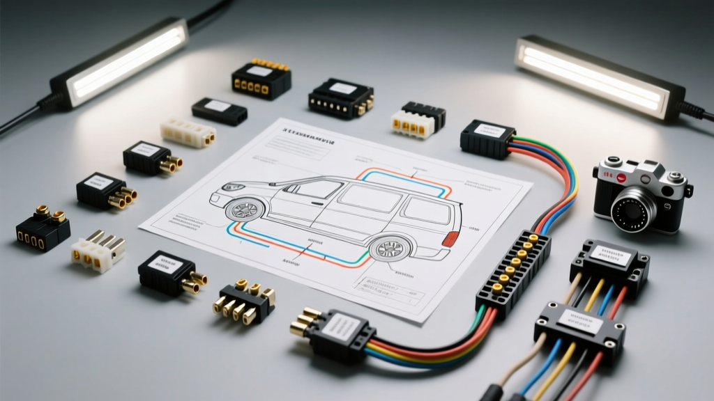
The Shift to Automotive-Grade Recessed Lighting in Commercial and Custom Vans
Customizing the cargo area of a Ford Transit, Mercedes-Benz Sprinter, or Ram ProMaster requires robust interior illumination. Unlike residential homes, vehicles subject wiring harnesses to severe vibration, thermal cycling, and extreme voltage fluctuations from the alternator. When sourcing a wiring diagram for recessed lighting, automotive builders and upfitters must reject residential 120V AC schematics in favor of SAE-compliant mobile 12V DC networks. Installing standard home puck lights in a work van or camper conversion is a primary cause of electrical fires and CAN-bus fault codes in modern commercial vehicles.
Product Comparison: 12V Recessed LED Puck Kits for Vehicle Interiors
Before selecting a wiring topology, you must choose the correct lighting hardware. The internal driver architecture of the recessed light dictates which wiring diagram you must use. Below is a comparison of the two primary product categories available to automotive upfitters.
1. Marine-Grade Stainless Steel 12V Puck Lights (Constant Current Driver)
- Architecture: Features an internal constant-current DC-DC buck converter.
- Voltage Tolerance: 9V to 32V DC. Easily absorbs the 14.4V+ spikes from a modern smart alternator.
- Wiring Requirement: Requires a simple switched 12V+ and Ground. Compatible with PWM dimmers without inducing flicker.
- Best Application: High-end Sprinter camper conversions, commercial ambulance patient compartments, and marine vessels.
2. RV-Grade Plastic Recessed LEDs (Resistor-Based)
- Architecture: Uses basic current-limiting resistors soldered directly to the LED diode array.
- Voltage Tolerance: Strictly 11.5V to 12.5V. If the van's alternator pushes 14.6V during bulk charging, the resistors overheat, causing premature diode failure or melted plastic housings.
- Wiring Requirement: Requires a dedicated voltage regulator or a strictly isolated 'house' battery bank that is not directly tied to the chassis alternator without a DC-DC charger.
- Best Application: Budget trailer builds or auxiliary battery setups with regulated 12V outputs.
Choosing the Correct Wiring Diagram for Recessed Lighting
The ideal wiring diagram for recessed lighting in a modern vehicle bypasses the factory headlight or dome light circuits entirely. Tapping into a modern CAN-bus controlled dome light circuit (such as those found in 2015+ Ford Transits or 2019+ Ram ProMasters) will trigger Body Control Module (BCM) fault codes and cause the lights to shut off after 10 minutes due to battery saver logic.
The Gold Standard: Upfitter Switch Trigger with ISO Relay
For commercial work trucks and vans, the safest and most reliable method is utilizing the factory Upfitter Switch module. This provides a clean, low-amperage trigger signal to an ISO relay, which then switches high-amperage 12V power directly from the battery to the recessed lighting array.
Step-by-Step: Executing the Upfitter Switch Wiring Diagram
Below is the standard execution for a Ford Transit (2015-Current) utilizing the overhead Aux Switch bank and the Customer Access Point (CAP) under the hood or behind the B-pillar.
- Identify the Trigger Wire: Locate the Upfitter Aux 1 trigger wire. According to the Ford Body Builder Layout Book, Aux 1 is typically Violet with a White stripe. This wire provides a 12V+ signal (max 2 Amps) only when the dash switch is toggled ON.
- Wire the ISO Mini Relay (Bosch Style 5-Pin):
- Pin 86 (Coil +): Splice into the Violet/White Upfitter trigger wire using a solder-seal heat shrink connector.
- Pin 85 (Coil -): Route to a clean, unpainted chassis ground using a ring terminal and a star washer to bite through the factory E-coat.
- Pin 30 (Common Power): Run 14 AWG SAE J1128 primary wire directly from the positive battery terminal or the main 12V distribution busbar. Install an inline 15A ATO blade fuse within 6 inches of the power source.
- Pin 87 (Normally Open Output): Run 14 AWG wire to the positive input of your recessed lighting harness.
- Grounding the Lighting Array: Do not daisy-chain grounds through sheet metal screws. Run a dedicated 14 AWG black ground wire from the negative terminal of the lighting array back to a centralized negative busbar, which is then tied to the main chassis ground stud.
Technical Specification Chart: AWG Sizing & Voltage Drop
When adapting a wiring diagram for recessed lighting to a long-wheelbase (LWB) or extended-length van (such as a 170-inch wheelbase Sprinter), voltage drop becomes a critical failure point. LEDs will flicker or shift color temperature if the voltage at the fixture drops below 11.5V under load. The following chart assumes a 12V DC system, a 15-amp continuous draw (typical for 15-20 high-output puck lights), and a maximum acceptable voltage drop of 2%.
| Total Wire Run Length (Source to Load + Ground Return) | Minimum AWG Size (SAE J1128) | Calculated Voltage Drop @ 15A | Recommended Fuse Size |
|---|---|---|---|
| Under 10 Feet | 14 AWG | 0.06V (0.5%) | 15A ATO |
| 10 to 20 Feet | 12 AWG | 0.12V (1.0%) | 20A ATO |
| 20 to 35 Feet (LWB Vans) | 10 AWG | 0.19V (1.5%) | 25A ATO |
| 35 to 50 Feet (Trailer/Bus) | 8 AWG | 0.24V (2.0%) | 30A ATO |
Note: Always calculate total circuit length by adding the positive wire run and the negative ground return run together. A 15-foot run from the battery to the rear doors of a Transit is actually a 30-foot circuit when factoring in the ground return.
Real-World Troubleshooting: CAN-Bus Interference and PWM Flickering
Automotive electrical environments are notoriously 'noisy'. If your recessed lighting exhibits ghosting (staying dimly lit when turned off) or high-frequency flickering, the issue is rarely the wiring diagram itself, but rather the components interacting with the vehicle's data bus.
1. Ghosting on Smart Alternator Systems
Modern vehicles use LIN-bus controlled smart alternators that vary voltage between 12.2V and 15.0V. If you are using a cheap mechanical toggle switch instead of an isolated relay, parasitic capacitance in long wire runs can trick sensitive LED drivers into glowing faintly. The Fix: Install a 10k-ohm, 1/2-watt bleed resistor in parallel across the positive and negative terminals at the furthest light fixture in the daisy chain to dissipate stored capacitive energy.
2. Dimming and PWM Flicker with Upfitter Modules
Some factory auxiliary switch modules use Pulse Width Modulation (PWM) to soft-start circuits or protect against shorts. If the wiring diagram for your recessed lighting includes an aftermarket PWM dimmer knob, the two PWM frequencies will clash, causing a strobe effect. The Fix: Use a constant-current relay bypass or ensure your aftermarket dimmer operates on high-frequency analog voltage reduction rather than digital PWM chopping.
Authoritative Standards and Connector Selection
Never use residential wire nuts or standard vinyl electrical tape in a vehicle harness. The constant vibration of a commercial chassis will cause wire nuts to back off, leading to high-resistance arcing. According to SAE J1128 standards for low-tension primary automotive cable, all wiring must utilize cross-linked polyethylene (XLPE) insulation to withstand engine bay and chassis heat up to 125°C.
For all connections in the cargo area where moisture and vibration are present, utilize Littelfuse and Deutsch DT series sealed connectors. Crimping Deutsch solid nickel pins with a proper pneumatic or ratcheting crimper ensures a gas-tight connection that will survive millions of vibration cycles over the lifespan of the fleet vehicle. For upfitter integration details specific to your chassis, always consult the manufacturer's Body Builder Layout Book, such as the Ford Truck BBAS portal, to verify exact wire colors, pinouts, and maximum allowable current draws for auxiliary circuits.