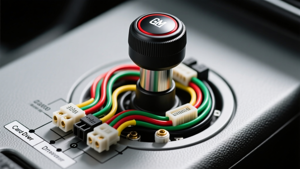
Decoding the Turn Signal Wiring Diagram
When analyzing a turn signal wiring diagram for North American vehicles, particularly classic and square-body General Motors platforms, you are not just looking at a simple lighting circuit. You are looking at a complex, integrated logic matrix. Unlike European vehicles that separate brake and turn signal circuits, North American DOT regulations allow for combined rear brake and turn signal functions. This requires the steering column switch to act as a mechanical logic gate, interrupting the brake light circuit on one side while simultaneously routing the flasher relay pulse to the same filament.
This complete walkthrough dissects the anatomy of the GM Saginaw steering column turn signal circuit. We will trace the current from the fuse panel, through the flasher relay, into the column bulkhead connector, and down to the 1157 dual-filament rear lamps. Whether you are restoring a 1980s C10 pickup or troubleshooting a parasitic draw in a 1990s B-body sedan, understanding this schematic is mandatory for any automotive electrical technician.
Core Circuit Architecture and Wire Gauges
Before diving into the switch matrix, we must establish the baseline electrical architecture. Automotive lighting circuits operate on a switched-ground or switched-power paradigm; GM turn signals utilize a switched-power, chassis-ground system.
- Main Power Feed (12 AWG): The primary feed from the battery to the fuse panel utilizes 12 AWG wire, capable of handling up to 41 amps, though the circuit is typically protected by a 20A fuse or a fusible link.
- Flasher to Column Feed (18 AWG): The wire routing from the flasher relay to the steering column is 18 AWG (usually GXL cross-linked polyethylene insulation). This wire must handle the inrush current of four 1157 bulbs (approximately 2.1 amps each on the bright filament, totaling 8.4 amps).
- Bulkhead Connectors: The wiring harness interfaces with the steering column via a multi-pin bulkhead connector (typically a 9-pin or 12-pin Saginaw connector). High resistance here is the leading cause of voltage drop and hyper-flashing.
Step-by-Step Turn Signal Wiring Diagram Walkthrough
Phase 1: Power Delivery and the Flasher Relay
The circuit begins at the fuse panel. A 20-amp fuse protects the Purple wire (18 AWG), which routes to the turn signal flasher relay. The flasher relay is traditionally a thermal-mechanical bimetallic strip device. When current flows, the strip heats up, bends, and breaks the circuit, extinguishing the bulbs. As the strip cools, it snaps back, completing the circuit and causing the familiar "click."
The output side of the flasher relay sends a pulsed 12V signal down the Purple wire directly to the steering column bulkhead connector. It is critical to note that the hazard flasher operates on a completely separate feed (typically a Brown wire) with its own dedicated relay and heavier fuse, as it must power all four corner lamps simultaneously.
Phase 2: The Saginaw Switch Matrix (The Logic Gate)
The Purple wire enters the turn signal switch housing. Inside, a series of copper wiper contacts ride on a phenolic resin cam attached to the turn signal lever. Simultaneously, the brake light switch at the pedal sends a constant 12V signal (when depressed) up the White wire into the exact same switch housing.
Here is where the magic of the turn signal wiring diagram occurs. In the neutral (center) position, the switch wiper physically bridges the White brake feed to both the Yellow (Left) and Dark Green (Right) output wires. When you pull the lever to the LEFT, the mechanical cam shifts. It physically disconnects the White brake feed from the Yellow wire, and instead connects the pulsed Purple flasher feed to the Yellow wire. The right side (Dark Green) remains connected to the brake feed. This prevents the rear bulbs from fighting between a solid 12V brake signal and a pulsed 12V turn signal.
Phase 3: Bulkhead Routing and Rear Lamp Integration
The Yellow and Dark Green wires exit the column, pass through the firewall bulkhead, and route to the rear of the vehicle. At the rear lamp housing, these wires terminate at the bright filament (usually the offset lower pin) of an 1157 or 3157 dual-filament bulb. The dim filament is fed by a Brown wire (running lights), and the bulb casing grounds directly to the vehicle chassis via a dedicated Black pigtail or socket retention springs.
GM Saginaw 9-Pin Turn Signal Connector Pinout Chart
The following table details the standard pinout for the classic GM 9-pin steering column connector specifically governing the turn, brake, and hazard circuits. Always verify with a multimeter, as aftermarket harnesses may deviate from OEM color codes.
| Pin / Circuit | OEM Wire Color | AWG | Function & Destination |
|---|---|---|---|
| Flasher Feed | Purple | 18 | Pulsed 12V from Turn Flasher Relay to Switch |
| Hazard Feed | Brown | 18 | Pulsed 12V from Hazard Flasher Relay to Switch |
| Brake Feed | White | 18 | Constant 12V from Brake Pedal Switch |
| Left Turn/Brake | Yellow | 18 | Output to Left Front and Left Rear Lamps |
| Right Turn/Brake | Dark Green | 18 | Output to Right Front and Right Rear Lamps |
| Left Front Park | Dark Blue | 18 | Dim filament feed for Left Front Marker |
| Right Front Park | Light Green | 18 | Dim filament feed for Right Front Marker |
| Column Ground | Black | 18 | Ground for Horn Relay and Switch Illumination |
| Ignition Feed | Pink/Black | 16 | Switched 12V for Cruise Control / Wiper Delay |
Real-World Failure Modes and Multimeter Diagnostics
When troubleshooting using a turn signal wiring diagram, never rely solely on visual bulb inspection. Use a digital multimeter (DMM) to perform voltage drop and continuity tests. Below is a diagnostic decision tree for the most common GM column failures.
Symptom: Hyper-Flashing (Fast Blink) on One Side
The Physics: A thermal flasher relay blinks faster when it detects lower amperage (less heat generated). This almost always means a bulb is out, or the circuit has high resistance.
- Test the Bulb: Remove the 1157 bulb. Check the bright filament for continuity. If intact, proceed.
- Test the Socket Ground: Set DMM to DC Volts. Place the red probe on the bright filament contact inside the socket and the black probe on a known good chassis ground (not the bulb housing). Activate the turn signal. If you read 11.5V+ but the bulb doesn't light when inserted, your socket ground is corroded. The current is seeking a path of least resistance back through the opposite side's filament (backfeeding).
- Test the Bulkhead Connector: Measure voltage drop across the column connector. Place one probe on the harness side Yellow wire and the other on the column side Yellow wire. A drop greater than 0.2V indicates oxidized copper pins requiring dielectric grease and tensioning.
Symptom: Turn Signal Cancels Brake Light on BOTH Sides
The Physics: If pulling the left turn lever causes the right brake light to go out, the mechanical isolation inside the Saginaw switch has failed.
- Disconnect the column bulkhead connector.
- With the brake pedal depressed, use a test light on the harness-side White wire to confirm 12V.
- Probe the harness-side Yellow and Dark Green wires. Both should illuminate the test light.
- If the right side (Dark Green) loses power when the left turn lever is pulled, the internal phenolic cam is cracked, or the copper wiper is bent, allowing the brake circuit to be severed globally. The steering column switch must be replaced.
Upgrading to LED and SAE Compliance
Modernizing classic vehicles with LED 1157 bulbs introduces a massive hurdle: current draw. A standard incandescent 1157 bulb draws roughly 2.1 amps on the bright filament. Four bulbs draw 8.4 amps. An LED equivalent draws less than 0.5 amps total. The thermal flasher relay will not heat up enough to break the circuit, resulting in the turn signals staying on solid without flashing.
To resolve this while maintaining compliance with SAE J589 standards for turn signal flash rates (60 to 120 flashes per minute), you have two options:
- Electronic Flasher Relay: Replace the thermal can with an electronic LED flasher (e.g., Novita EL13 or Tridon EP34). These use a solid-state 555 timer IC to pulse the circuit regardless of amperage draw.
- Load Resistors: If you must retain the thermal relay, wire a 6-ohm, 50-watt ceramic load resistor in parallel with each rear turn signal bulb. This mimics the electrical load of an incandescent filament. Warning: These resistors generate extreme heat and must be bolted to bare metal chassis, never zip-tied to plastic or wiring harnesses.
For comprehensive wiring schematics and deep-dive troubleshooting on classic GM steering columns, the archives at MAD Electrical remain an industry-standard reference for restorers and custom fabricators. Furthermore, any modifications to exterior lighting must adhere to NHTSA FMVSS 108 regulations regarding luminosity and color separation to ensure street legality.