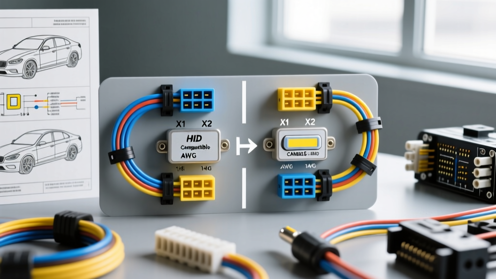
The Critical Role of Ballast Architecture in Automotive Lighting
Upgrading your vehicle’s lighting system from halogen to High-Intensity Discharge (HID) or high-output LED requires more than simply swapping bulbs. The heart of any high-voltage or high-current lighting conversion is the ballast or driver module. Understanding the specific ballast diagram wiring for your chosen product is critical to avoiding dashboard errors, flickering, and melted harnesses. Whether you are retrofitting a 2014 Jeep Wrangler with a TIPM (Totally Integrated Power Module) or upgrading a BMW F-Series with a multiplexed FRM (Footwell Module), selecting the correct ballast architecture dictates your wiring strategy.
This product comparison and selection guide breaks down the electrical requirements, connector types, and wiring schematics of the most common automotive ballasts on the market. By consulting authoritative resources like the Hella Automotive Electronics Technical Library, we can map out exactly how to match the right ballast to your vehicle's specific electrical topology.
Core Ballast Types: A Comparative Overview
When evaluating products, the internal circuitry of the ballast determines the external wiring complexity. Here is a comparison of the three primary ballast categories and how their wiring diagrams differ.
1. Standard Electronic Ballasts (Non-CANBUS)
Standard electronic ballasts are the most basic and cost-effective options. They feature a simple two-wire input: 12V+ and Ground. During ignition, a standard 35W HID ballast will spike to draw between 10 to 15 amps for 200-400 milliseconds before settling at a steady-state draw of roughly 3.2 amps. The ballast diagram wiring for these units is straightforward, but they lack the internal resistance required to satisfy modern vehicle bulb-check algorithms, often triggering "Bulb Out" warnings on the dash.
2. CANBUS Integrated Ballasts
CANBUS (Controller Area Network) ballasts feature internal resistors or digital handshake microchips designed to mimic the electrical load of a standard 55W halogen bulb. The wiring diagram for a CANBUS ballast often includes a PWM (Pulse Width Modulation) feedback loop. In advanced OEM setups, the ballast diagram wiring may incorporate dedicated CAN-High and CAN-Low data lines to communicate directly with the vehicle’s body control module (BCM), reporting operating temperature and bulb status in real-time.
3. Anti-Flicker / PWM Decoder Ballasts
Vehicles manufactured by Chrysler, Dodge, and Jeep frequently use Pulse Width Modulation (PWM) to operate headlights, rapidly pulsing the voltage to extend bulb life and monitor the circuit. A standard ballast will interpret this pulsing as a faulty connection, resulting in severe flickering. Anti-flicker ballasts feature large inline capacitors (usually 4700µF to 10000µF) or heavy-duty resistors in their wiring schematic to smooth the PWM signal into a steady 12V DC current before it reaches the igniter.
Decoding the Ballast Diagram Wiring: Connectors & Pinouts
The physical interface between the vehicle harness and the ballast is a common point of failure. Selecting a ballast with the correct OEM-style connector prevents the need for cutting and splicing factory wires. Below is a comparison of standard connector types found in ballast wiring schematics.
| Connector Type | Pin Configuration | Wire Colors (Typical OEM) | Primary Application |
|---|---|---|---|
| AMP / Hirschmann (2-Pin) | Pin 1: 12V+ Pin 2: Ground |
Red/White (Power) Brown/Black (Ground) |
Aftermarket HID kits, basic 9006/H11 conversions. |
| OEM D1S / D2S (4-Pin) | Pin 1: 12V+ Pin 2: Ground Pin 3: Igniter Trigger Pin 4: Feedback |
Red (Power), Brown (Ground) Green (Trigger), Yellow (Feedback) |
Factory HID systems (Audi, VW, Lexus). Integrates the igniter into the ballast housing. |
| Hella 5DS / 7DS (3-Pin) | Pin 1: 12V+ Pin 2: Ground Pin 3: PWM/CAN Signal |
Red/White (Power), Brown (Ground) Blue/Green (Signal) |
European multiplexed systems requiring BCM handshake. |
| Deutsch DT (4-Pin) | Pin 1: 12V+ Pin 2: Ground Pin 3: CAN-H Pin 4: CAN-L |
Red (Power), Black (Ground) White (CAN-H), Green (CAN-L) |
Heavy-duty trucks, off-road LED ballasts, and advanced CANBUS networks. |
Wire Gauge, Insulation, and Routing Specifications
A frequent mistake in aftermarket lighting installations is using undersized wiring. According to the SAE J1128 Low Tension Cable Standard, automotive wire must be rated for high-temperature engine bay environments. When extending or modifying your ballast diagram wiring, adhere to the following specifications:
- Power Feed (Battery to Relay): Use 12 AWG or 10 AWG stranded copper wire with SXL (Cross-linked polyethylene) insulation. SXL insulation is rated up to 125°C, which is vital when routing near exhaust manifolds or turbochargers.
- Relay to Ballast Input: 14 AWG is the minimum requirement for 35W ballasts. If you are running 55W ballasts (which draw up to 5.5A steady-state and 20A on ignition), upgrade to 12 AWG to prevent voltage drop.
- Grounding Protocol: Never ground a ballast to a painted surface or a thin sheet-metal screw. The ballast diagram wiring must terminate at a dedicated chassis ground stud using a 14 AWG wire with a closed-loop ring terminal. Secure with a star washer and torque to 8-10 Nm to ensure a zero-resistance path.
- Ignition Spike Mitigation: Because HID ignitors require up to 25,000 volts to strike the xenon arc, the high-voltage output cables must be kept at least 2 inches away from the vehicle’s ECU, ABS module, and radio antenna cables to prevent Electromagnetic Interference (EMI).
Vehicle-Specific Selection Guide: Matching the Ballast to the ECU
Selecting the right ballast requires understanding how your specific vehicle monitors its lighting circuits. The AutoShop 101 Automotive Electrical Guide outlines how modern Body Control Modules (BCM) utilize cold and hot resistance checks to verify bulb integrity.
Scenario A: Chrysler / Dodge / Jeep (TIPM Systems)
The Problem: The TIPM sends a brief 12V pulse to check for a short circuit before applying full PWM power. If it detects the low initial resistance of an aftermarket ballast, it shuts the circuit down entirely.
The Selection: You must select a ballast with an integrated Anti-Flicker capacitor module, or wire an external PWM decoder inline before the ballast's power input. The wiring diagram must show the decoder receiving the PWM signal and outputting a smoothed DC voltage to the ballast.
Scenario B: BMW / Mini (FRM / BDC Modules)
The Problem: BMW’s Footwell Module (FRM) or Body Domain Controller (BDC) actively monitors the CANBUS network for the specific digital signature of an OEM HID ballast. If the signature is missing, the FRM cuts power to prevent perceived electrical fires.
The Selection: Standard CANBUS resistors will not work here. You must select a "Digital CANBUS" ballast featuring an ASIC (Application-Specific Integrated Circuit) chip programmed to emulate the exact I2C/CAN handshake of an OEM Osram or Hella ballast. Alternatively, the wiring must be routed to a bypass harness that taps into a non-monitored 12V accessory circuit, triggered by a relay.
Real-World Troubleshooting & Failure Modes
Even with the correct product selection, improper execution of the ballast diagram wiring can lead to systemic failures. Use this diagnostic matrix to troubleshoot common issues:
Symptom: Headlight Ignites, Flickers, and Shuts Off After 3 Seconds
- Cause: Voltage drop on the ground circuit during the high-amperage ignition spike. The ballast’s internal low-voltage protection triggers a shutdown.
- Fix: Measure the voltage drop across the ground wire while cranking the ignition. If the drop exceeds 0.2V, clean the chassis ground point, add a star washer, or run a dedicated 12 AWG ground wire directly to the negative battery terminal.
Symptom: Dashboard "Bulb Out" Warning Illuminates
- Cause: The BCM detects a lower-than-expected current draw on the lighting circuit, meaning the ballast lacks sufficient internal CANBUS load.
- Fix: Install a 6-ohm, 50W ceramic wire-wound resistor in parallel with the ballast’s power and ground wires. Warning: These resistors generate extreme heat (up to 150°C). Mount them to a metal chassis bracket, never near plastic trim or wiring harnesses.
Symptom: Radio Static or ABS Warning Lights Trigger When Headlights Turn On
- Cause: High-voltage EMI from the HID igniter or poor shielding on the ballast's internal switching transformer is bleeding into the vehicle's data bus.
- Fix: Verify that the high-voltage cables are not zip-tied to OEM sensor harnesses. Wrap the ballast’s 12V input wires in copper-foil shielding tape and ground the foil to the chassis to contain the EMI.
Conclusion
Mastering the nuances of ballast diagram wiring is the difference between a factory-quality lighting upgrade and an electrical nightmare. By comparing the internal architecture of Standard, CANBUS, and PWM-decoding ballasts, and strictly adhering to SAE wiring standards for gauge and insulation, you can ensure reliable, high-performance illumination. Always verify your vehicle's specific BCM monitoring logic before purchasing a ballast, and prioritize high-quality, sealed connectors like Deutsch DT or OEM Hirschmann plugs to guarantee long-term weatherproof reliability.