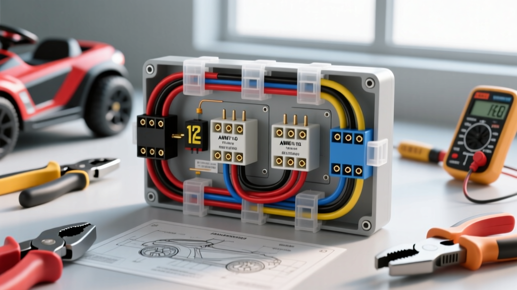
Decoding the Power Wheels 12V Ride On Car Wiring Diagram
When analyzing a power wheels 12v ride on car wiring diagram, it is critical to approach the vehicle's electrical system with the same rigor used in full-sized automotive 12V DC platforms. While these are classified as toy vehicles, the underlying physics of direct current (DC), voltage drop, inrush amperage, and thermal limits are identical to automotive auxiliary circuits. Factory wiring diagrams typically reveal a simplistic architecture: an 18 AWG wire harness, a mechanical foot pedal switch, a 6-pin DPDT (Double Pole Double Throw) forward/reverse rocker switch, and a 30A auto-resetting thermal breaker.
However, when owners upgrade to high-capacity 12V 14Ah SLA (Sealed Lead Acid) batteries or install dual 550-size DC motors, the factory diagram becomes a liability. The stock foot pedal switches are notorious failure points; they are not rated for the 20A+ continuous draw of upgraded motors, leading to melted plastic housings and arced contacts. This cost and tool requirements analysis will break down exactly what is needed to properly repair, rewire, or upgrade a 12V ride-on chassis safely and efficiently.
Tool Requirements for 12V Toy Vehicle Wiring
Executing a reliable wiring harness upgrade requires moving beyond basic electrical tape and wire nuts. Automotive-grade 12V DC systems demand secure mechanical and soldered connections to withstand the high-frequency vibrations and physical shocks inherent to off-road ride-on use. Below is an analysis of the essential tools required, alongside estimated costs for a professional-grade bench setup.
| Tool Category | Specific Tool Requirement | Estimated Cost | Application in 12V DC Wiring |
|---|---|---|---|
| Wire Preparation | Self-Adjusting Wire Strippers (10-22 AWG) | $25 - $40 | Stranding 12 AWG and 14 AWG stranded copper without nicking the conductors. |
| Termination | Heavy-Duty Crimper with Heat Shrink Die | $35 - $60 | Crimping ring terminals and spade connectors for relay harnesses. |
| Soldering | 60W+ Temperature-Controlled Soldering Station | $50 - $90 | Tinning battery leads and soldering high-amperage XT60 connectors. |
| Diagnostics | True-RMS Digital Multimeter (DMM) | $40 - $120 | Measuring voltage drop across the DPDT switch and testing relay coil continuity. |
| Insulation | Heat Gun with Reflector Nozzle | $30 - $50 | Shrinking adhesive-lined marine heat shrink over XT60 and ring terminals. |
Material Cost Breakdown: OEM Repair vs. 12V Performance Upgrade
The cost to rewire a 12V Power Wheels chassis varies drastically depending on whether you are restoring the factory diagram or engineering a high-amperage performance harness. According to SAE J1128 standards for low-tension primary cable, wire gauge must be selected based on the maximum continuous amperage draw and the total length of the circuit to prevent excessive voltage drop.
Scenario A: Stock OEM Repair (Standard 12V Single Motor)
Restoring a factory harness for a standard 12V, single-motor setup (drawing roughly 10A-15A under load) requires basic components. The factory relies on Molex-style connectors and 18 AWG wire. While cheap, these connectors suffer from high contact resistance over time due to corrosion and vibration.
- 18 AWG Stranded Wire (Red/Black): $12.00
- OEM Replacement Foot Pedal Switch: $8.50
- 30A Auto-Reset Thermal Breaker: $7.00
- Molex Connector Kit: $10.00
- Total Estimated Material Cost: ~$37.50
Scenario B: High-Amp 12V Performance Upgrade (Dual Motor / 14Ah Battery)
Upgrading the diagram to support dual 550 motors or high-torque gearbox modifications requires bypassing the weak foot pedal switch using automotive relays. This setup utilizes standard ATO blade fuses and heavy-duty XT60 connectors to ensure zero voltage drop at the battery terminals.
- 12 AWG Silicone Stranded Wire: $22.00
- XT60 Connectors (Male/Female Pairs): $12.00
- Bosch-Style 5-Pin 12V 30A Relays (x2): $14.00
- Heavy-Duty Relay Sockets with Pigtails: $16.00
- 30A ATO Blade Fuse & Weatherproof Holder: $9.50
- Adhesive-Lined Marine Heat Shrink Kit: $15.00
- Total Estimated Material Cost: ~$88.50
Wire Gauge (AWG) and Voltage Drop Considerations
A common failure mode in modified 12V ride-on cars is motor bogging and overheating wires. This is rarely a motor issue; it is a voltage drop issue caused by undersized wiring. When a 12V motor pulls 25 Amps through 6 feet of 16 AWG wire (total circuit length including ground), the voltage drop can exceed 1.5 Volts. This leaves the motor receiving only 10.5V under load, drastically reducing torque and causing the wire insulation to melt.
| Wire Gauge (AWG) | Max Continuous Ampacity | Voltage Drop per 10ft @ 20A | Recommended Application |
|---|---|---|---|
| 18 AWG | 10 Amps | 1.28 Volts | Low-draw accessories (horns, LED lights, sound modules) |
| 16 AWG | 15 Amps | 0.80 Volts | Stock single-motor 12V setups (short runs) |
| 14 AWG | 20 Amps | 0.51 Volts | Standard dual-motor 12V setups |
| 12 AWG | 30 Amps | 0.32 Volts | High-performance 12V upgrades, main battery feeds |
Step-by-Step Relay Upgrade Wiring (Pinout Configuration)
To eliminate the melting foot pedal switch, the upgraded wiring diagram utilizes the pedal switch merely as a low-amp trigger for a standard ISO mini automotive relay. The relay handles the heavy amperage directly from the battery to the DPDT switch and motors.
Bosch-Style 5-Pin Relay Pinout:
- Pin 30 (Common): Connect directly to the 12V+ battery terminal via a 30A ATO fuse.
- Pin 87 (Normally Open): Connect to the input terminal of the DPDT Forward/Reverse switch.
- Pin 86 (Coil 12V+): Connect to the output side of the foot pedal switch.
- Pin 85 (Coil Ground): Connect to the main chassis ground or battery negative.
- Pin 87a (Normally Closed): Unused in this specific high-amp motor configuration; tape off and secure.
How it works: When the child presses the foot pedal, a negligible current (less than 0.2A) flows through Pin 86 to Pin 85, energizing the internal electromagnet. This pulls the contactor from Pin 87a to Pin 87, allowing the full 30A capacity to flow from the battery directly to the drive motors, completely bypassing the fragile plastic contacts of the foot pedal.
DPDT Switch Polarity Crossover (Forward/Reverse)
The 6-pin DPDT rocker switch controls motor direction by reversing the DC polarity. The wiring requires an 'X' crossover pattern on the switch terminals: 1. Top Center Pins: Power input from Relay Pin 87 (12V+) and Main Ground. 2. Middle Left/Right Pins: Output to Motor A and Motor B. 3. Bottom Left/Right Pins: Jumper wires crossed in an 'X' pattern back to the opposite Middle pins. This crossover ensures that flipping the rocker switch swaps the positive and negative leads at the motor terminals, reversing the magnetic field and the vehicle's direction.
Troubleshooting Common 12V Power Wheels Failures
Even with a perfect wiring diagram, 12V DC systems are prone to specific environmental and mechanical failures. Use this diagnostic tree to isolate issues:
- Symptom: Vehicle clicks but does not move.
Cause: Tripped thermal breaker or blown ATO fuse due to a locked rotor (e.g., grass or debris jamming the gearbox).
Fix: Clear debris, check motor continuity with a DMM, and replace the fuse if the short is cleared. - Symptom: Vehicle only drives in reverse, or one motor spins backward.
Cause: Incorrect DPDT crossover wiring or a melted internal contact in the rocker switch causing a phase short.
Fix: Verify the 'X' jumper pattern on the DPDT switch pins. Replace the switch if continuity tests fail in the forward position. - Symptom: XT60 battery connector is hot to the touch and smells of ozone.
Cause: Cold solder joint inside the XT60 housing creating high contact resistance.
Fix: Cut off the damaged XT60. Strip the 12 AWG silicone wire, tin the leads heavily, and solder the new XT60 ensuring the solder flows completely into the brass bullet cavity before cooling.
By treating the power wheels 12v ride on car wiring diagram as a serious automotive electrical schematic, builders can drastically increase the reliability, safety, and lifespan of the vehicle, ensuring that the electrical harness outlasts the mechanical gearboxes and plastic chassis.