The Overland Challenge: Residential Fridges in Automotive Environments
Integrating a residential 120V AC appliance into a 12V or 24V DC automotive electrical system requires a fundamental understanding of both vehicle alternator output and AC compressor surge dynamics. Modern expedition vehicles, custom Sprinter van builds, and heavy-duty truck campers frequently utilize residential refrigerators due to their superior capacity and cost-effectiveness compared to native 12V compressor fridges. However, powering a high-surge AC compressor from a mobile DC battery bank introduces severe electrical challenges. If the DC-to-AC inversion topology and vehicle-side cabling are not engineered to handle the intense inrush current of a compressor startup, the result will be tripped inverters, damaged start capacitors, and potentially catastrophic DC electrical fires.
The Misconception of the Appliance Schematic
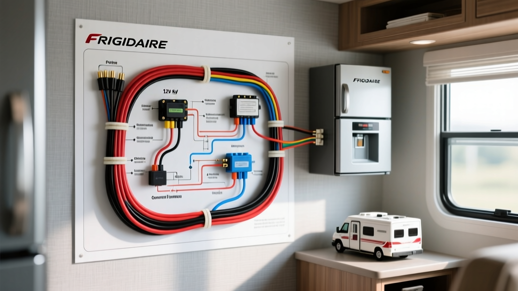
When custom upfitters, van-lifers, and expedition builders search for a wiring diagram for frigidaire refrigerator installations, they are typically directed to internal appliance schematics meant for HVAC repair technicians. These internal diagrams detail the defrost timer, PTC start relay, evaporator fan motors, and internal 120V AC routing. While useful for diagnosing a broken compressor, these internal schematics are entirely useless for the automotive electrical engineer. From a vehicle integration perspective, the critical diagram is the 12V DC to 120V AC power delivery network. The vehicle's electrical system must be treated as a localized micro-grid, capable of delivering massive surge amperage on the DC side to satisfy the AC side's inductive load. This guide provides the technical specification reference for wiring the vehicle-side power delivery, ignition-sense relays, and AC chassis bonding required to safely run a residential Frigidaire refrigerator off a vehicle's battery bank.
Vehicle-Side DC Power Delivery Schematic
The most common failure point in overland refrigerator setups is undersized DC cabling between the battery bank and the inverter. A standard 18 to 20 cubic foot Frigidaire refrigerator draws approximately 3 to 4 Amps (360W to 480W) during steady-state operation. However, the compressor's start capacitor requires a massive surge of 1200W to 1500W for up to three seconds during startup. On a 12V DC system, a 1500W surge translates to roughly 125 Amps of instantaneous DC current draw, not accounting for inverter inefficiencies. Therefore, the DC wiring must be sized not for the running wattage, but for the continuous peak capacity of the inverter itself.
DC Cable Sizing and Voltage Drop Calculations
For a 3000W Pure Sine Wave inverter powering a residential fridge, 4/0 AWG SAE J1128 stranded copper battery cable is the minimum acceptable standard for runs up to 15 feet. Using smaller gauge wire will result in severe voltage drop, causing the inverter's low-voltage cutoff to trigger the moment the fridge compressor attempts to start.
| Component | Specification | Technical Justification |
|---|---|---|
| DC Cable | 4/0 AWG SAE J1128 | Handles up to 300A continuous; minimizes voltage drop under compressor surge. |
| DC Overcurrent Protection | 500A Class T Fuse | Class T fuses have a 20,000 AIC (Ampere Interrupting Capacity) rating, essential for lithium battery fault currents. ANL fuses are insufficient for high-capacity lithium banks. |
| Busbars | 600A Stud Type (3/8'') | Provides centralized distribution; prevents daisy-chaining of high-current lugs. |
| Lug Crimping | Hydraulic Hex Crimp + Adhesive Heat Shrink | Mil-Spec crimping ensures zero air pockets; adhesive shrink prevents galvanic corrosion. |
All busbar connections must be torqued to manufacturer specifications, typically 12 ft-lbs for 3/8'' studs, to prevent micro-arcing and thermal runaway under heavy DC loads.
Inverter Ignition-Sense and Remote Relay Wiring
Leaving a 3000W inverter powered on continuously will drain a vehicle's battery bank through the inverter's no-load parasitic draw. To automate the system, automotive electricians utilize a Bosch-style 5-pin SPDT relay to trigger the inverter's remote on/off terminal only when the vehicle's engine is running and the alternator is charging. This ignition-sense logic is critical for expedition vehicles that rely on the chassis alternator to recharge the house batteries while driving.
Pinout Configuration for Alternator-Triggered Inverter
Using a standard 12V 40A automotive relay, wire the inverter remote trigger circuit as follows:
- Pin 86 (Coil Power): Connect to a 12V+ ignition-switched source. In modern vans like the Ford Transit or Mercedes Sprinter, tap into an upfitter auxiliary switch circuit or the alternator D+ terminal to ensure the relay only energizes when the engine is actively running.
- Pin 85 (Coil Ground): Connect to a clean, bare-metal vehicle chassis ground point. Use a self-tapping grounding screw with star washer and anti-oxidant paste.
- Pin 30 (Switch Common): Connect to a 12V+ constant battery source via an inline 5A ATC fuse. This provides the trigger voltage that will be sent to the inverter.
- Pin 87 (Normally Open): Connect directly to the inverter's 'Remote On/Off' or 'Ignition Sense' positive trigger terminal. When the coil energizes, Pin 30 bridges to Pin 87, waking the inverter.
- Pin 87a (Normally Closed): Left unused and insulated in this specific application.
AC Output Wiring and Chassis Bonding
The AC output from the inverter to the refrigerator receptacle must be treated with the same rigor as residential home wiring, adapted for mobile environments. Use 12 AWG THHN stranded copper wire routed through flexible non-metallic conduit to protect against chassis vibration and chafing. The circuit must be protected by a dedicated 20A GFCI breaker mounted within 18 inches of the inverter's AC output terminals.
Grounding and neutral bonding in mobile AC systems is a frequent source of confusion. According to ABYC E-11 standards and the Victron Energy Wiring Unlimited Guide, the inverter's internal neutral-to-ground relay must be allowed to function correctly. The inverter chassis must be bonded to the vehicle's DC chassis ground using a minimum 6 AWG copper wire. This ensures that if an internal AC fault occurs within the Frigidaire refrigerator, the fault current has a low-resistance path back to the DC battery bank, tripping the inverter's internal breaker instantly and preventing the fridge exterior from becoming electrically 'hot'.
Troubleshooting Compressor Surge and Harmonic Distortion
Residential Frigidaire compressors are highly sensitive to the quality of the AC sine wave. Using a Modified Sine Wave (MSW) inverter will cause severe harmonic distortion. This distortion forces the compressor motor to run 20% to 30% hotter, degrades the internal winding insulation, and frequently destroys the PTC start relay, resulting in a compressor that clicks but fails to turn over. Always specify a Pure Sine Wave inverter with a Total Harmonic Distortion (THD) of less than 3%.
Troubleshooting Decision Tree: Compressor Clicks but Fails to Start
| Symptom | Probable Automotive Cause | Diagnostic Step |
|---|---|---|
| Rapid clicking at fridge rear; compressor hums briefly then stops. | Voltage drop at inverter AC output; MSW inverter damaging PTC relay; or DC voltage sag triggering inverter protection. | Measure AC RMS voltage at fridge plug under load. Must remain above 110V. Measure DC voltage at inverter lugs during startup; must not drop below 10.5V. |
| Inverter faults immediately on compressor start (Overload Alarm). | Insufficient DC surge current capacity; undersized battery bank BMS limits; or high DC cable resistance. | Verify battery BMS continuous discharge rating. Check 4/0 AWG crimps for thermal hotspots using an infrared thermometer. |
| Fridge runs but freezes food inconsistently; compressor runs continuously. | Modified Sine Wave causing compressor motor overheating and thermal cutoff; or inadequate ventilation in the vehicle cabinetry. | Verify inverter topology via oscilloscope. Ensure 2-inch minimum clearance around fridge condenser coils for airflow. |
Alternator and Lithium BMS Considerations
When wiring a high-capacity inverter to a vehicle's starter battery to charge the house bank via a DC-DC charger while running the fridge, alternator protection is paramount. Modern vehicle alternators are not designed for continuous 100% duty cycle output. If the Frigidaire compressor kicks on simultaneously with a 60A DC-DC charger pulling from the chassis battery, the combined load can exceed a standard 140A alternator's capacity, leading to alternator diode failure. Always install a high-idle module or utilize a smart BMS that can throttle DC-DC charging rates dynamically based on the vehicle's real-time electrical load.
Authoritative References
- Victron Energy Wiring Unlimited Guide - Comprehensive reference for DC-to-AC inversion, neutral bonding, and mobile grounding topologies.
- Blue Sea Systems Circuit Protection Guidelines - ABYC standards for Class T vs. ANL fusing in high-fault-current lithium environments.
- SAE J1128 Low-Tension Battery Cable Specifications - Engineering standards for automotive battery cable insulation, temperature ratings, and AWG stranding requirements.