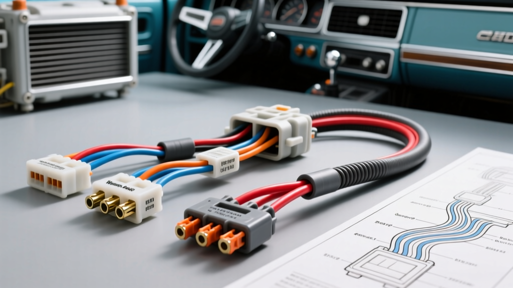
Introduction to the GM Square Body AC Electrical System
The 1973-1987 GM C/K 'Square Body' trucks are legendary for their durability, but their 40-year-old electrical systems—particularly the climate control circuits—are highly susceptible to high-resistance faults, melted bulkhead connectors, and failed grounds. When restorers and mechanics attempt to diagnose a non-functioning compressor clutch or a blower motor that only works on high speed, they quickly realize that referencing a generic 73 87 chevy truck air conditioning wiring diagram is only the first step. The true challenge lies in executing the repair using the correct terminal crimping tooling and sourcing components that meet original equipment (OE) current-carrying specifications.
This guide approaches the GM Square Body AC wiring system from a Cost & Tool Requirements Analysis perspective. We will break down the exact wire color codes, circuit topology, mandatory Weather-Pack tooling, and a realistic budget for restoring your AC harness to factory-fresh reliability without cutting corners.
Decoding the AC Circuit Topology & Wire Color Codes
The factory air conditioning system on the 73-87 C/K trucks relies on a relatively simple series circuit for compressor engagement, paired with a dedicated high-current relay for the blower motor. Understanding the routing from the fuse block to the compressor clutch is critical for voltage drop testing.
Compressor Clutch Control Circuit
- Power Feed (Fuse Block to HVAC Switch): Orange (14 AWG) - Provides 12V constant or ignition-switched power depending on the exact model year and fuse block configuration.
- HVAC Switch to Low-Pressure Cycling Switch: Light Blue (16 AWG) - Routes through the firewall bulkhead connector to the accumulator-mounted cycling switch.
- Low-Pressure Switch to Thermal Limiter: Dark Green (16 AWG) - Exits the cycling switch and travels to the compressor-mounted thermal limiter switch.
- Thermal Limiter to Clutch Coil: Dark Green (16 AWG) - Completes the positive side of the circuit to the electromagnetic clutch coil.
- Ground Path: The clutch coil grounds directly through the compressor casting to the engine block. Expert Note: Corrosion between the compressor mounting bracket and the engine block is a primary cause of 'no-engagement' faults. Always run a dedicated 12 AWG Black ground wire from the compressor case to the alternator bracket if the factory ground path exceeds 0.1V drop.
Blower Motor High-Speed Relay Circuit
A common failure point in these trucks is the HVAC selector switch melting on the 'High' setting. This happens because the switch attempts to carry the full amperage of the blower motor. GM implemented a relay to bypass the switch contacts for high-speed operation.
| Circuit Path | OEM Wire Color | AWG Size | Function |
|---|---|---|---|
| Battery to Relay (Power) | Red | 10 AWG | High-amperage feed directly from the battery/junction block. |
| HVAC Switch to Relay (Trigger) | Yellow | 16 AWG | 12V signal from the switch to energize the relay coil. |
| Relay to Blower Motor | Purple | 14 AWG | Delivers full 12V to the blower motor, bypassing the resistor block. |
| Relay Ground | Black | 16 AWG | Grounds the relay coil to the dash frame. |
Tool Requirements: The GM Weather-Pack Imperative
You cannot properly service a 1973-1987 GM wiring harness with generic, open-barrel crimpers. The factory connectors are Delphi (Packard) Weather-Pack sealed connectors, utilizing 5.6mm (0.220-inch) closed-barrel terminals. These terminals require a specific double-crimp: one barrel grips the copper conductor, while the second barrel crushes the insulation and the integrated silicone weather seal.
Using a standard $15 open-barrel crimper will deform the terminal, preventing it from locking into the nylon housing and compromising the weather seal. This allows moisture intrusion, leading to green copper oxidation (copper carbonate) inside the connector, which increases resistance and eventually melts the plastic housing due to heat buildup.
Mandatory Tooling Checklist
- Ratcheting Weather-Pack Crimper: Must feature the specific 'W' or hexagonal die for 16-14 AWG closed-barrel terminals. (Estimated Cost: $65 - $130)
- Terminal Extraction Tool: A specialized pick tool to depress the nylon locking tang inside the Weather-Pack housing without snapping the brittle, 40-year-old plastic. (Estimated Cost: $12 - $25)
- Dielectric Grease: Nyogel 760G or equivalent. Never use standard silicone grease, which can degrade certain elastomers over time. (Estimated Cost: $18)
- Heat Shrink & Adhesive: For any inline splices made in the engine bay. Dual-wall, adhesive-lined heat shrink is mandatory to prevent capillary action from drawing water under the insulation. (Estimated Cost: $22)
Cost Analysis: Restoration vs. Patch Repair
When budgeting an AC electrical restoration on a Square Body, owners generally choose between patching individual faults or replacing the entire harness. Below is a realistic cost breakdown comparing OEM-style restoration parts versus budget aftermarket alternatives.
| Component / Service | Budget Aftermarket | OEM / Premium Restoration | Expert Recommendation |
|---|---|---|---|
| Complete Engine Bay AC Harness | $85 - $120 | $210 - $280 (e.g., Mads Electrical) | Premium. Cheap harnesses use undersized 18 AWG wire and non-ratcheting terminals that fail within 2 years. |
| HVAC Selector Switch (Dash) | $25 | $65 (Standard Motor Products) | Premium. Budget switches have weak internal detents and high-resistance brass contacts. |
| Compressor Clutch Coil | $18 | $45 (Delco / OEM) | Premium. Ensure the coil resistance reads between 3.5 and 4.5 ohms at 68°F. |
| Weather-Pack Terminal Kit (50pc) | $15 | $35 (Delphi Genuine) | Premium. Aftermarket seals often lack the correct durometer to seal against the nylon housing. |
| Firewall Bulkhead Connector | N/A (Usually Patched) | $140 (Lectric Limited) | Restoration. The bulkhead is the #1 failure point. Do not bypass it; replace the halves. |
Note: Pricing is based on current market averages for GM C/K restoration components. Reference Mads Enterprises and Lectric Limited for exact Square Body harness applications.
Advanced Troubleshooting: Firewall Bulkhead & Relays
If you have verified the wiring diagram, confirmed your tools are correct, and invested in quality components, but the AC still fails to engage, the fault likely lies in the firewall bulkhead connector. On 73-87 trucks, the main wiring harness passes through the firewall via a large, multi-pin plastic block. Over decades, engine bay heat cycles and vibration cause the female terminals in this bulkhead to lose their spring tension.
The Voltage Drop Test Protocol
Do not use a simple test light; a test light will illuminate even if the circuit has enough resistance to drop the voltage below the threshold required to energize the AC clutch coil (which typically requires a minimum of 10.5V under load).
- Set your digital multimeter to DC Volts.
- Connect the black probe to the battery negative terminal.
- Back-probe the Light Blue wire at the accumulator low-pressure switch with the red probe.
- Turn the ignition to 'ON', set the HVAC switch to 'A/C', and the blower to 'Low'.
- Expected Reading: 12.2V - 12.6V.
- Fault Reading: Anything below 11.0V indicates high resistance upstream, almost certainly located at the firewall bulkhead connector or the HVAC selector switch contacts.
If high resistance is found at the bulkhead, you must extract the terminals using your Weather-Pack pick tool, clean them with electrical contact cleaner, and gently squeeze the female terminal boxes with needle-nose pliers to restore tension before reassembling with Nyogel 760G dielectric grease.
SAE & GM Service Manual References
When sourcing wire for custom AC harness repairs, ensure the primary cable meets SAE J1128 specifications for low-tension primary automotive cable, which dictates the insulation thickness, temperature rating (up to 125°C for engine bay routing), and copper stranding requirements. Furthermore, restorers should consult the GM Heritage Center archives for original 1973-1987 Chassis Service Manuals to verify exact pin-cavity assignments, as GM frequently mid-year updated the bulkhead cavity layouts between 1981 and 1983 during the transition to computer-controlled engine management systems.
By combining the correct 73 87 chevy truck air conditioning wiring diagram data with professional-grade Weather-Pack tooling and OE-specification components, you eliminate the high-resistance faults that plague the Square Body platform, ensuring your AC system operates reliably for decades to come.