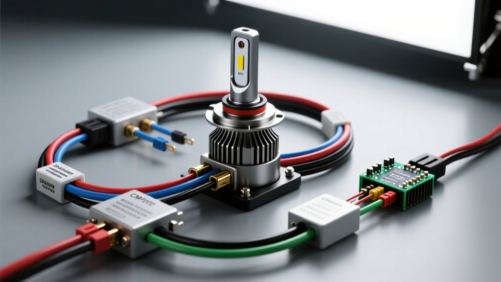
Introduction to HID (Xenon) Electrical Architecture
High-Intensity Discharge (HID) lighting, commonly referred to as Xenon, represents a fundamental shift from simple resistive filament circuits to complex, high-voltage AC power management systems. When analyzing an OEM or aftermarket HID headlight wiring diagram, technicians must understand that the system does not operate on standard 12V DC. Instead, it relies on a sophisticated ballast to manage three distinct electrical phases: the 23,000V ignition spike, the high-current run-up phase, and the steady-state 85V RMS AC square wave operation.
Unlike halogen systems where a simple relay and switch dictate power delivery, HID circuits require precise microprocessor control to monitor arc tube impedance, manage color temperature shifts, and communicate with the vehicle’s Body Control Module (BCM). According to Hella TechWorld's Xenon Systems documentation, the ballast acts as a localized power inverter and diagnostic node, making the wiring harness a critical data and power conduit rather than a mere electrical extension.
OEM HID Headlight Wiring Diagram: Core Circuit Topology
A standard factory HID headlight wiring diagram centers around the electronic ballast, typically mounted in a dry zone beneath the headlight housing or within the front bumper fascia. The primary input harness usually consists of a 3-pin or 4-pin sealed connector (often TE Connectivity AMP Superseal or Sumitomo HM series).
Standard 3-Pin Ballast Input Pinout (e.g., Hella 5DV / Matsushita)
- Pin 1 (Terminal 30 / B+): Constant 12V battery feed. Protected by a 10A or 15A fuse in the front power distribution center. Wire color is typically Red or Red/White (14 AWG).
- Pin 2 (Terminal 31 / GND): Chassis ground. Must maintain a voltage drop of less than 0.05V under load. Wire color is universally Brown or Black (14 AWG).
- Pin 3 (Terminal 15 / Signal): Switched 12V ignition or BCM wake-up signal. In modern CANBUS architectures, this may carry a low-current PWM logic signal rather than a direct high-current power feed. Wire color is often Blue/Yellow or Green/White (18 AWG).
In vehicles equipped with Adaptive Front-lighting Systems (AFS), a 4th or 5th pin is introduced to carry LIN-bus (Local Interconnect Network) data, allowing the BCM to command swivel angles and dynamic leveling directly to the headlight's internal stepper motors.
D1S vs. D2S vs. D3S vs. D4S: High-Voltage Secondary Pinouts
The secondary side of the HID headlight wiring diagram connects the ballast to the igniter, and the igniter to the Xenon bulb. The architecture changes drastically depending on the bulb designation. Daniel Stern’s comprehensive HID technical guide highlights the critical safety and electrical differences between integrated and external igniter systems.
| Bulb Type | Igniter Location | Ballast-to-Igniter Wiring | Operating Voltage | Ignition Spike |
|---|---|---|---|---|
| D1S / D1R | Integrated (Base of bulb) | 2-Pin heavy gauge (AC Square Wave) | 85V RMS | 23,000V (Generated at bulb) |
| D2S / D2R | External (Inline or Ballast-mounted) | 2-Pin high-voltage silicone coaxial | 85V RMS | 23,000V (Generated at igniter) |
| D3S / D3R | Integrated (Mercury-Free) | 4-Pin shielded (Includes data/feedback) | 42V RMS | 25,000V (Requires higher spike) |
| D4S / D4R | External (Mercury-Free) | 2-Pin high-voltage silicone coaxial | 42V RMS | 25,000V |
Technical Warning: D3S and D4S bulbs are mercury-free and operate on a completely different AC voltage curve (42V RMS vs 85V RMS). Plugging a D3S bulb into a D1S ballast wiring harness will result in immediate bulb destruction and potential ballast MOSFET failure due to impedance mismatch.
Aftermarket Relay Harness & CANBUS Integration
When executing an HID retrofit on modern vehicles (2010+ European and North American platforms), the factory halogen wiring diagram is inadequate. Modern BCMs utilize Pulse Width Modulation (PWM) on the low-beam circuits to perform cold and warm bulb diagnostics. The BCM sends a rapid 400Hz to 600Hz PWM signal, measuring the voltage drop to verify filament resistance.
The PWM Conflict and CANBUS Error Cancellation
An HID ballast presents a massive capacitive and inductive load. When the BCM sends a PWM diagnostic pulse, the ballast's internal capacitors absorb the spike, causing a phase shift and an inrush current that the BCM interprets as a short circuit. This results in the BCM cutting power to the headlight circuit entirely, manifesting as flickering, strobing, or a "Bulb Out" dash warning.
To resolve this, the retrofit HID headlight wiring diagram must incorporate a CANBUS decoder or a heavy-duty relay harness. The correct wiring topology involves:
- Isolating the BCM: Using the factory low-beam positive wire solely as a low-current trigger signal for an automotive 40A SPDT relay.
- Dedicated Power Feed: Running a fused 10 AWG wire directly from the battery (Terminal 30) to the relay's power input, bypassing the BCM's delicate PWM traces.
- Capacitive Load Emulation: In vehicles where the BCM requires a specific resistive load to clear the dash code (e.g., Dodge/Chrysler TIPM systems), a 50W 6-ohm wirewound resistor must be wired in parallel with the relay trigger circuit to simulate a halogen filament's thermal resistance.
Wire Gauge (AWG) and Routing Specifications
Voltage drop is the silent killer of HID systems. According to Bosch Mobility Solutions automotive lighting standards, HID ballasts require a minimum of 11.5V at the input terminals during the run-up phase to successfully transition the Xenon arc from a metallic vapor state to a stable plasma state. If voltage drops below 10.5V, the arc will extinguish, and the ballast will lock out to protect the igniter.
| Circuit Segment | Recommended AWG | Insulation Type | Max Allowable Voltage Drop |
|---|---|---|---|
| Battery to Relay (Primary Feed) | 10 AWG | XLPE or Cross-linked PVC | 0.20V |
| Relay to Ballast (Power/Ground) | 14 AWG | Standard PVC (GXL/SGX) | 0.15V |
| BCM Trigger Signal | 18 AWG | Standard PVC | N/A (Logic Level) |
| Ballast to Igniter (High Voltage) | N/A (Specialized) | Silicone Dielectric (25kV rated) | N/A |
Routing the high-voltage secondary wires requires strict adherence to bend radius limits. Kinking the silicone coaxial cables can compromise the internal dielectric shielding, leading to arc tracking (where the 23,000V spike grounds out through the moisture on the outside of the wire to the chassis), which causes a no-start or severe radio frequency interference (RFI) condition.
Diagnostic Troubleshooting: Real-World Failure Modes
Troubleshooting an HID circuit using a standard digital multimeter (DMM) is largely ineffective and potentially dangerous. A standard DMM cannot accurately read the high-frequency AC square wave output of the ballast, nor can it survive the 23,000V ignition spike if probing the secondary side.
Oscilloscope Diagnostics (PicoScope / Snap-on Scope)
To properly diagnose a failing HID headlight wiring harness or ballast, an automotive oscilloscope with high-voltage differential probes is required.
- Ignition Phase Verification: Connect the scope to the primary input. Upon activation, you should see a clean 12V DC line that dips momentarily to ~10.5V as the ballast draws up to 15A of inrush current for 0.5 seconds.
- Steady-State Square Wave Analysis: Using a 1000:1 high-voltage differential probe on the secondary output, a healthy D1S/D2S ballast will display a symmetrical AC square wave oscillating between +120V and -120V (yielding ~85V RMS) at a frequency of 200Hz to 400Hz.
- Asymmetrical Waveform Faults: If the oscilloscope reveals a skewed or asymmetrical square wave (e.g., +140V / -90V), the internal MOSFET H-bridge within the ballast is failing, or the Xenon bulb's internal electrode is degrading, causing unequal impedance in the arc tube. This is the primary cause of "color shifting" (where the bulb turns pink or purple) before total failure.
Ground Circuit Degradation
Because HID systems operate on AC, a poor ground connection does not just cause dimming; it causes severe waveform distortion. The ballast's internal feedback loop will attempt to compensate for the floating ground by increasing output voltage, eventually triggering the ballast's internal over-voltage protection and shutting the system down. Always perform a loaded voltage drop test on Pin 2 (Ground) using a 10A halogen test light before condemning an HID ballast.