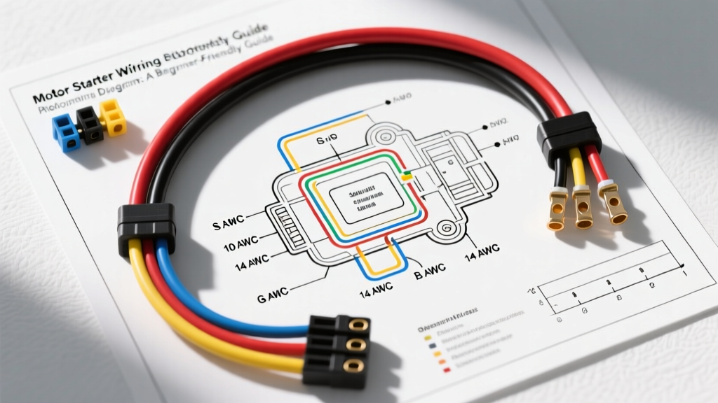
Understanding the Motor Starter Wiring Diagram
For any automotive DIYer or beginner technician, the starting system is one of the most critical circuits to master. Unlike low-amperage sensor circuits, the starter motor demands massive current—often exceeding 250 amps during the initial cranking phase. Reading a motor starter wiring diagram is the first step toward diagnosing no-crank conditions, upgrading high-torque starters, or installing remote start systems. This guide breaks down the fundamental architecture of starter circuits, solenoid terminal designations, and the specific AWG (American Wire Gauge) requirements needed to safely route high-amperage DC power.
The Core Architecture of a Starter Circuit
Before tracing lines on a schematic, you must understand the physical components that make up the system. A standard starter circuit consists of five primary elements:
- The Battery: The high-capacity DC power source.
- The Main Power Cable: A heavy-gauge conductor routing 12V+ directly to the starter solenoid.
- The Ignition Switch & Safety Interlocks: Low-amperage switches that initiate the crank signal, routed through the Neutral Safety Switch (NSS) or Clutch Pedal Position (CPP) switch.
- The Starter Relay / Solenoid: An electromagnetic switch that bridges the high-amperage main power to the starter motor while simultaneously engaging the pinion gear with the flywheel.
- The Engine Ground Strap: The return path to the battery negative terminal.
Decoding Solenoid Terminals: The Alphabet of Cranking
The most confusing part of any motor starter wiring diagram for beginners is the lettering on the solenoid. Whether you are working on a classic GM Delco 10MT or a modern Denso gear-reduction unit, the terminal designations follow a standardized logic.
Standard 3-Post and 4-Post Solenoid Terminals
| Terminal | Name | Function & Wire Spec | Typical OEM Wire Color (GM/Ford) |
|---|---|---|---|
| B | Battery | Main 12V+ input from the battery positive post. Requires 1/0 AWG or 2 AWG cable per SAE J1127 standards. | Unshielded Black or Red (Heavy Cable) |
| S | Start / Switch | Receives the 12V+ signal from the ignition switch/relay to energize the solenoid coil. Uses 12 AWG or 10 AWG wire. | Purple (GM) / Red-Light Blue (Ford) |
| I | Ignition (Bypass) | Provides a full 12V+ bypass to the ignition coil during cranking, compensating for the voltage drop of the ballast resistor in points-style systems. Uses 16 AWG. | Yellow or Brown (16 AWG) |
| R | Retard / Run | Cuts power to accessories (like AC or radio) during cranking to maximize available amperage for the starter. Rarely used on modern vehicles. | N/A |
| M | Motor | The output terminal connecting the solenoid to the starter motor housing. Usually a short, heavy braided copper strap or a 1/0 AWG jumper. | N/A (Internal Strap or Heavy Jumper) |
Note: When tightening the B-terminal nut on a Delco Remy solenoid, do not exceed 120 in-lbs of torque. Overtightening will strip the internal copper threads and ruin the solenoid assembly.
Fender-Mounted vs. Starter-Mounted Solenoids
When reviewing wiring diagrams, you will notice two distinct architectural layouts depending on the vehicle manufacturer.
1. Starter-Mounted Solenoids (GM / Chrysler / Most Imports)
In this design, the solenoid is bolted directly to the starter motor housing. The heavy 1/0 AWG battery cable connects directly to the B-terminal on the starter. The S-terminal receives the low-amperage signal from the ignition relay. Because the heavy cable is always "hot" and runs the entire length of the vehicle to the starter, proper insulation and routing away from exhaust headers are critical to prevent catastrophic short circuits.
2. Fender-Mounted Relays (Classic Ford / Heavy Duty Trucks)
Ford historically used a heavy-duty relay mounted on the inner fender well. The battery cable connects to the relay's input stud. A second heavy cable runs from the relay's output stud to the starter motor. The starter motor itself has a simple grounding strap or a short jumper from its own solenoid. In this diagram, the ignition switch triggers the fender relay, which then sends high-amperage current down the secondary heavy cable to crank the engine. This keeps the heavy, always-hot cable shorter and reduces voltage drop.
Wire Gauge Selection and Voltage Drop
Beginners often make the mistake of using undersized wire for starter upgrades. According to Haynes Automotive Electrical Basics, wire gauge must be selected based on both amperage draw and cable length. A standard 5.0L V8 starter pulls roughly 180-220 amps under load. A high-torque aftermarket mini-starter for a supercharged application can pull 300+ amps.
- Battery to Starter (Main Feed): Minimum 2 AWG for runs under 6 feet; 1/0 AWG for runs over 6 feet or high-draw diesel applications.
- Engine Block to Chassis Ground Strap: Must match the main positive feed (1/0 AWG or 2 AWG braided copper). A poor ground is responsible for over 40% of all "dead starter" misdiagnoses.
- Ignition Signal Wire (S-Terminal): 12 AWG is standard. Using 16 AWG for long runs can result in voltage drop, causing the solenoid to chatter or fail to engage.
Troubleshooting the Starter Circuit with a Multimeter
When your motor starter wiring diagram checks out visually but the vehicle won't crank, you must perform a Voltage Drop Test. Never simply measure battery voltage; measure the voltage lost across connections while the circuit is under load (cranking).
Voltage Drop Decision Tree
- Place the red multimeter lead on the battery positive post and the black lead on the starter B-terminal. Have an assistant crank the engine.
- Result > 0.5V: You have excessive resistance in the main positive cable or battery terminals. Clean terminals or replace the 1/0 AWG cable.
- Place the red lead on the starter motor case (clean bare metal) and the black lead on the battery negative post. Crank the engine.
- Result > 0.2V: The engine ground strap is corroded, loose, or undersized. The starter is trying to ground through the engine mounts, which will cause erratic cranking and mount degradation.
- Check the S-Terminal Signal. Back-probe the S-terminal wire while cranking.
- Result < 10.5V: Voltage is dropping through the ignition switch, neutral safety switch, or starter relay. Bypass the NSS with a jumper wire to isolate the faulty safety interlock.
Safety Interlocks: The Hidden Diagram Components
A complete motor starter wiring diagram will always include safety interlocks. If you turn the key to "Start" and hear absolutely nothing (no relay click, no solenoid clack), the issue is rarely the heavy cables—it is almost always the control circuit. Modern vehicles route the S-terminal signal through the PCM (Powertrain Control Module), the Transmission Range Sensor (Park/Neutral), and the anti-theft immobilizer. When tracing a no-crank fault, always consult the factory service manual to locate the exact pinout for the PCM starter relay control wire, as jumping the wrong 12V+ signal into a 5V logic circuit will instantly destroy the engine computer.
Summary for Beginners
Mastering the motor starter wiring diagram requires understanding the separation of the high-current cranking circuit and the low-current control circuit. Always respect the AWG requirements for main power and ground straps, memorize the B, S, I, and M solenoid terminals, and rely on voltage drop testing rather than visual inspections. For deeper technical specifications on starter torque curves and bench-testing procedures, refer to the Delco Remy Starting System Troubleshooting Guide.