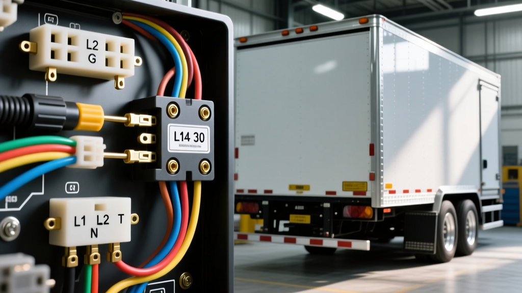
Introduction to the NEMA L14-30P Configuration
When outfitting heavy-duty enclosed car haulers, mobile automotive detailing units, or fifth-wheel RVs with robust shore power, the NEMA L14-30 locking plug is the undisputed industry standard. Delivering 30 amps at 125/250 volts, this 4-pole, 4-wire configuration provides two independent 125V hot legs, a dedicated neutral, and a reliable equipment ground. Understanding the exact wiring diagram for L14 30 plug installations is critical to preventing catastrophic phase-to-phase shorts, ensuring proper operation of dual-voltage trailer appliances, and maintaining compliance with National Electrical Code (NEC) standards.
Unlike standard residential 3-prong dryer plugs, the L14-30P features a twist-lock mechanism that prevents accidental disconnects while navigating rough terrain or vibrating down the highway. In automotive and trailer applications, this plug is typically mated to an L14-30R flanged inlet mounted to the exterior of the trailer, feeding an internal sub-panel that distributes power to interior LED lighting, hydraulic liftgate motors, and 120V power tools.
L14-30 Plug Pinout and Terminal Identification
The NEMA L14-30P utilizes a specific pin geometry to prevent cross-mating with other voltage or amperage configurations. The plug face features four blades of varying shapes and sizes, corresponding to four internal terminal screws. Proper identification of these terminals is the first step in our wiring diagram walkthrough.
Terminal Mapping and Color Code Table
| Terminal ID | Screw Color | Standard Wire Color | Function | Voltage Potential |
|---|---|---|---|---|
| X | Brass | Black | Hot Leg 1 | 125V to Neutral / 250V to Y |
| Y | Brass | Red | Hot Leg 2 | 125V to Neutral / 250V to X |
| W | Silver | White | Neutral | 0V (Current Carrying) |
| G | Green | Green | Equipment Ground | 0V (Safety Fault Path) |
Note: The 'G' pin is the longest and thickest blade, designed to make first contact and break last when inserting or removing the plug from the receptacle, ensuring the chassis is grounded before the hot legs energize.
Cable Selection and Voltage Drop Considerations
Before executing the wiring diagram for your L14 30 plug, selecting the correct flexible cord is paramount. According to the NFPA 70 National Electrical Code (NEC) Article 400, the minimum allowable conductor size for a 30-amp circuit is 10 AWG copper. However, automotive and trailer environments demand flexible, highly durable jackets.
We strongly recommend using 10/4 SOOW (Service, Oil, Oil-resistant, Water/Weather-resistant) portable cord. The SOOW jacket features heavy-duty thermoset rubber that withstands abrasion from diamond-plate trailer floors, exposure to automotive fluids, and extreme UV radiation.
Voltage Drop Warning: While 10 AWG is code-compliant for runs up to 50 feet, mobile auto shops and large car haulers often require longer cord runs from a remote generator or shop pedestal. A 30-amp load on 60 feet of 10 AWG copper will result in a voltage drop of approximately 4.5 volts (3.6% on a 125V leg). To maintain optimal performance for sensitive automotive diagnostic computers and battery chargers, upgrade to 8/4 SOOW for any run exceeding 40 feet. The L14-30P terminal clamps can accommodate up to 8 AWG wire, though you may need to trim a few strands or use a step-down ferrule for a perfect fit.
Step-by-Step Wiring Diagram Walkthrough
Follow this precise sequence to terminate your L14-30P plug safely and reliably.
Phase 1: Cable Preparation and Strain Relief
- Disassembly: Remove the center retaining screw from the face of the L14-30P plug and slide the internal terminal block out of the outer rubber housing.
- Jacket Stripping: Using a rotary cable stripper, remove exactly 2.5 inches of the outer SOOW jacket. Be extremely careful not to nick the insulation of the four internal conductors.
- Conductor Stripping: Strip 1/2 inch of insulation from the Black, Red, White, and Green wires. If using stranded wire, twist the strands tightly or, preferably, crimp a 10 AWG insulated pin ferrule onto each conductor to prevent strand fraying under the terminal screws.
- Cord Grip Assembly: Slide the outer rubber housing and the internal strain relief cord grip onto the cable before making any electrical connections. This is the most common mistake made by novice installers.
Phase 2: Conductor Termination and Torque Specs
Route the wires into the terminal block according to the pinout table above. The internal block is typically marked with 'X', 'Y', 'W', and 'G' stamped directly into the phenolic resin.
- Black (X): Insert into the Brass terminal marked X.
- Red (Y): Insert into the Brass terminal marked Y.
- White (W): Insert into the Silver terminal marked W.
- Green (G): Insert into the Green terminal marked G.
Critical Torque Specification: According to Hubbell Wiring Device-Kellems technical specifications, the terminal screws for #10 AWG conductors must be tightened to 14 to 16 inch-pounds. Under-torquing leads to high-resistance connections, arcing, and melted plug faces. Over-torquing can strip the brass threads or shear the screw head. Use a calibrated inch-pound torque screwdriver for this step.
Once terminated, slide the cord grip up to the base of the terminal block, ensuring it bites down firmly on the outer SOOW jacket (not the individual wires). Tighten the cord grip assembly and re-insert the block into the rubber housing, securing it with the center faceplate screw.
Common Automotive and Trailer Applications
The L14-30P is heavily utilized in the automotive sector for specific high-draw applications:
- Enclosed Car Haulers: Powering interior LED work lights, 120V air compressors, and 12-volt DC battery chargers via an onboard converter.
- Mobile Detailing & Ceramic Coating Units: Providing simultaneous power to heated pressure washers, industrial vacuum extractors, and forced-air polishers without tripping standard 15A or 20A residential breakers.
- Mobile Command & Diagnostic Trucks: Supplying clean, split-phase 125/250V power to sensitive ECU flashing laptops, oscilloscopes, and server racks housed in custom transit vans.
Troubleshooting Voltage Drops and Phase Errors
Even with a perfect wiring diagram execution, environmental factors and upstream panel errors can cause issues. Use a Category III (CAT III) digital multimeter to verify your installation before plugging into expensive automotive equipment.
Multimeter Testing Decision Tree
- Test 1: Hot to Neutral (X to W, and Y to W)
- Expected Reading: 120V - 125V AC.
- If Reading is 0V: Check upstream breaker. Verify White (Neutral) is securely terminated at both the plug and the sub-panel bus bar. A floating neutral will cause severe voltage fluctuations.
- If Reading is 240V: The Neutral and Ground are swapped at the source receptacle, or the W terminal is mistakenly wired to a hot leg.
- Test 2: Hot to Hot (X to Y)
- Expected Reading: 240V - 250V AC.
- If Reading is 0V: Both hot legs are tied to the same phase upstream (common in improperly wired portable generators). Your 240V equipment (like large air compressors) will not start, and your neutral wire will carry the sum of both leg currents, risking a fire.
- Test 3: Hot to Ground (X to G, and Y to G)
- Expected Reading: 120V - 125V AC.
- If Reading is 0V or erratic: You have an open ground. Inspect the Green wire termination at the G pin. Ensure the trailer chassis is properly bonded to the sub-panel ground bus.
Authoritative References and Standards
To ensure your mobile electrical systems remain safe and legally compliant, always cross-reference your installations with the latest industry standards. The dimensional and spacing requirements for the L14-30 plug are strictly governed by the NEMA WD-6 Wiring Devices Dimensional Requirements standard. Furthermore, all overcurrent protection, wire sizing, and mobile home/trailer bonding rules must adhere to the latest edition of the NFPA 70 National Electrical Code, specifically Article 550 covering mobile homes and manufactured vehicle power feeds.
By adhering to this complete wiring diagram for L14 30 plug setups, utilizing high-quality SOOW cabling, and applying precise torque specifications, you guarantee a reliable, spark-free power delivery system capable of handling the rigorous demands of the automotive and heavy-haul industries.