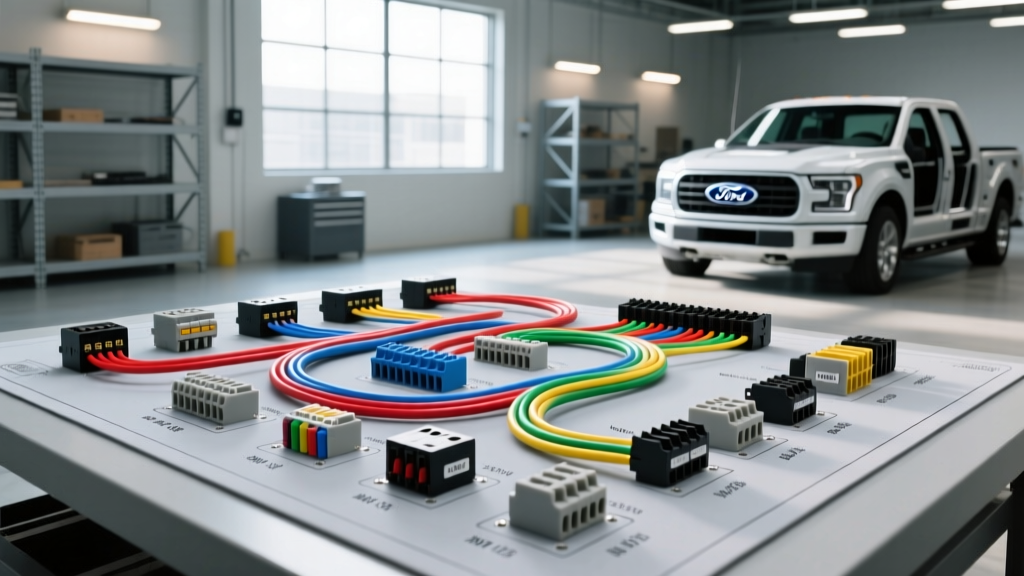
Navigating the 2024 Ford Upfitter Switches Wiring Diagram PDF
For commercial fleet managers, off-road enthusiasts, and upfitters, integrating auxiliary lighting, winches, and pneumatic controllers into a modern truck requires a precise understanding of the factory electrical architecture. When sourcing the official 2024 Ford upfitter switches wiring diagram PDF, technicians are not just looking at simple copper traces; they are interacting with the Body Equipment Module (BEM) and the vehicle's high-speed CAN bus network. The 2024 Ford Super Duty (F-250/F-350/F-450) and F-150 utilize an overhead console or dash-mounted 6-switch AUX bank that communicates via LIN/CAN protocols to trigger low-side solid-state drivers located in the engine bay.
Unlike older generation trucks where a physical switch directly routed 12V+ to a relay coil, the 2024 platform uses multiplexed signals. The factory blunt-cut wires located near the driver's side firewall are ground-triggered outputs. Selecting the correct wiring harness, relay kit, and wire gauge is critical to prevent back-feeding voltage into the BEM, which can cause catastrophic module failure. This guide compares OEM and aftermarket wiring solutions, decodes the factory pinouts, and provides the actionable data found in the manufacturer's upfitter schematics.
OEM Wire Color Codes and BEM Pinout Reference
The official Ford upfitter schematics detail the blunt-cut pigtail located under the hood, typically routed through the main firewall grommet or secured to the driver's side inner fender well. These wires are low-side triggers, meaning they provide a switched ground path when the corresponding AUX button is pressed on the dash. Below is the standardized color code reference for the 2024 model year upfitter outputs.
| Switch ID | Dash Label | Wire Color (OEM) | Circuit Function | Max Continuous Draw |
|---|---|---|---|---|
| AUX 1 | Switch 1 | Violet / White (VT/WH) | Low-Side Relay Trigger (Ground) | 15 Amps |
| AUX 2 | Switch 2 | Brown / White (BN/WH) | Low-Side Relay Trigger (Ground) | 15 Amps |
| AUX 3 | Switch 3 | Green / White (GN/WH) | Low-Side Relay Trigger (Ground) | 15 Amps |
| AUX 4 | Switch 4 | Yellow / White (YE/WH) | Low-Side Relay Trigger (Ground) | 15 Amps |
| AUX 5 | Switch 5 | Orange / White (OG/WH) | Low-Side Relay Trigger (Ground) | 10 Amps |
| AUX 6 | Switch 6 | Gray / White (GY/WH) | Low-Side Relay Trigger (Ground) | 10 Amps |
Note: Always verify wire colors against your specific VIN's build sheet, as mid-year production variations can occur. The definitive reference remains the Ford Fleet Upfitter Portal, which hosts the model-specific BEM wiring PDFs.
Product Selection: OEM Pigtails vs. Aftermarket Relay Harnesses
When planning your auxiliary accessory installation, you must choose between utilizing the factory-provided blunt-cut wires or purchasing an aftermarket plug-and-play relay harness. Each approach has distinct advantages depending on the complexity of your build.
Option A: OEM Ford Blunt Cut Pigtail Integration
Ford provides a blunt-cut wire harness taped back along the main engine bay wiring loom. To use this, you must splice into the VT/WH, BN/WH, etc., wires to trigger your aftermarket relays.
- Pros: Zero additional cost; utilizes factory-engineered firewall routing; maintains OEM warranty on the cab-side harness.
- Cons: Requires cutting, stripping, and soldering/heat-shrinking in tight engine bay spaces; requires the installer to supply their own 12V+ power distribution block and ground bus.
- Best For: Custom fabricators, commercial fleet upfitters building bespoke PTO or crane controls, and installers comfortable with soldering and adhesive-lined heat shrink.
Option B: Aftermarket Plug-and-Play Upfitter Harness Kits
Companies like Painless Performance and Carling Technologies offer harnesses that plug directly into the BEM or utilize inline T-taps specifically designed for the Ford upfitter circuits. These kits include pre-wired ISO mini relays, fused power distribution blocks, and Deutsch connectors.
- Pros: Drastically reduces installation time; includes pre-crimped weather-pack terminals; integrated 30A/40A Bosch-style relays and inline MAXI fuses.
- Cons: Higher upfront cost ($150 - $350); aftermarket loom tape and conduit may not match OEM routing standards.
- Best For: Weekend warriors, overland builds, and DIYers installing LED light bars, winch solenoids, and onboard air compressors who want a guaranteed, fused connection without cutting factory wires.
Wire Gauge Selection & Load Management
A common mistake when reading the 2024 Ford upfitter switches wiring diagram PDF is assuming the factory trigger wires can handle the full amperage of the accessory. The OEM VT/WH (Violet/White) wires are typically 14 AWG and are designed only to trigger a relay coil (which draws less than 150mA). The heavy current must be pulled directly from the battery or the BEM's high-current stud.
Adhering to SAE J1128 standards for low-tension primary cable is critical for voltage drop mitigation, especially in high-ambient-temperature environments like a Super Duty engine bay.
| Accessory Type | Max Draw | Trigger Wire (BEM to Relay) | Main Power (Battery to Load) | Recommended Relay |
|---|---|---|---|---|
| LED Light Bar (40") | 12A | 18 AWG (Spliced to OEM 14 AWG) | 12 AWG | Standard 40A ISO Mini |
| Winch Contactor | 250A+ (Solenoid draw: 5A) | 16 AWG | 2 AWG (Direct to Winch) | 70A Continuous Duty Solenoid |
| Onboard Air Compressor | 30A | 18 AWG | 10 AWG | Heavy Duty 50A Relay |
| Work Lights (Halogen) | 25A | 18 AWG | 10 AWG | Standard 40A ISO Mini |
Relay Pinout Configuration for Low-Side Triggers
Because the 2024 Ford upfitter system uses low-side (ground) switching, your relay wiring must be configured correctly to avoid short circuits. When using a standard 5-pin Bosch-style ISO mini relay, the pinout mapping is as follows:
- Pin 86 (Relay Coil 12V+): Connect to a switched 12V+ source or a fused constant 12V+ battery terminal.
- Pin 85 (Relay Coil Ground): Connect to the Ford Upfitter Trigger Wire (e.g., VT/WH for AUX 1).
- Pin 30 (Common Power Input): Connect to the main fused 12V+ power distribution block.
- Pin 87 (Normally Open Output): Connect to the positive terminal of your accessory.
- Pin 87a (Normally Closed): Leave insulated and unused.
Critical Warning: If you reverse Pins 85 and 86, or mistakenly send 12V+ into Pin 85 while the BEM is attempting to ground the circuit, you will instantly fry the internal solid-state driver inside the Body Equipment Module. Always use a digital multimeter (DMM) to verify the trigger wire drops to near 0.00V (ground) when the dash switch is activated, and reads 12V+ (open circuit/floating) when off.
BEM Software Configuration and Failure Modes
Installing the physical wiring is only half the battle. The 2024 Ford BEM requires software configuration to dictate how the AUX switches behave. If your truck was not ordered with the Upfitter package from the factory, but you have retrofitted the overhead console and BEM, the switches will remain inactive until configured.
FDRS and FORScan Configuration
To enable the switches, alter battery-saver timeouts, or change a switch from 'Latching' to 'Momentary' (crucial for winch controls or horn triggers), you must interface with the OBD-II port. Dealerships use the official Ford Diagnostic and Repair System (FDRS), while advanced DIYers utilize SEMA Garage approved tools like FORScan to modify the BEM As-Built data. Parameters such as AUX_SW_TIMEOUT can be adjusted to prevent the BEM from cutting power to accessories like auxiliary fuel pumps or refrigeration units when the ignition is in the 'RUN' position but the engine is off.
Common Troubleshooting Decision Tree
If your auxiliary accessories fail to engage after installation, follow this diagnostic sequence:
- Symptom: Dash switch illuminates, but accessory does not turn on.
Cause: Blown main inline fuse, or Pin 30 on the relay lacks 12V+.
Fix: Test voltage at the distribution block. Check the MAXI fuse. - Symptom: Accessory turns on, but dash switch LED flickers or BEM throws a CEL.
Cause: Inductive kickback from the relay coil damaging the BEM driver.
Fix: Ensure your aftermarket relay has an internal suppression diode or install a flyback diode across Pins 85 and 86 (stripe facing Pin 86). - Symptom: Switch works for 30 seconds, then shuts off automatically.
Cause: BEM Battery Saver logic is active.
Fix: Use FORScan to disable the battery saver timeout for that specific AUX channel in the BEM module configuration.
Final Upfitter Routing and Sealing Best Practices
When routing your 12 AWG or 10 AWG power wires from the engine bay to the cab or rear of the truck, never pierce the factory Ford upfitter grommets with a screw or zip-tie. Use a blunt awl and lubricate the wire with dielectric grease or silicone spray to pass through the rubber firewall grommet. Once inside, seal the puncture with RTV silicone to prevent carbon monoxide and water ingress. By combining the precise data from the 2024 Ford upfitter switches wiring diagram PDF with the correct relay harness and gauge selection, you ensure a reliable, dealership-grade electrical integration for any accessory.