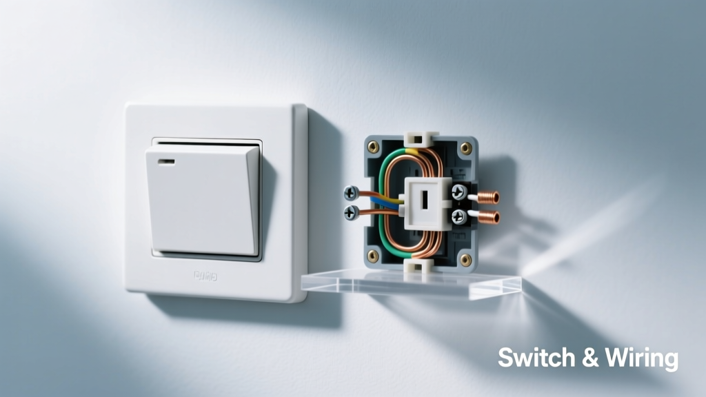
Core Functional Distinctions Between Switches and Wiring
Switches and wiring serve fundamentally different but interdependent roles in automotive electrical systems. A switch is an active control device that initiates, interrupts, or redirects current flow upon user or system input; wiring is a passive conductive pathway designed to transmit electrical energy with minimal loss. While both are essential for circuit operation, their design intent, failure mechanisms, and service implications differ significantly. For example, the ignition switch in a 2023 Toyota Camry handles up to 40 A at 12.6 V DC during cranking but must withstand over 100,000 actuation cycles per OEM specification (JIS D5401:2021). In contrast, the main battery-to-starter cable in the same vehicle—a 35 mm² cross-section copper conductor—is rated for continuous 180 A operation with peak surge tolerance of 750 A for 5 seconds, per SAE J1127 standard. Confusing their functions leads to misdiagnosis: a no-start condition attributed to ‘bad wiring’ may actually stem from internal contact erosion inside the starter relay switch, where contact resistance exceeds 50 mΩ—well above the 5 mΩ maximum specified by ISO 8820-2.
Electrical Ratings: Voltage, Current, and Thermal Limits
Automotive switches and wiring are engineered to distinct electrical envelopes. Wiring specifications prioritize ampacity, voltage drop, and thermal dissipation over time. For instance, Ford’s 2024 F-150 uses 12 AWG (3.31 mm²) GXL primary wiring for headlight circuits, rated for 25 A continuous duty at 105°C ambient per SAE AS50881. That same wire exhibits only 3.2 mV drop per meter at 15 A—critical for maintaining LED headlight brightness within ±5% tolerance. Conversely, the multifunction turn-signal stalk switch in the F-150 contains six independent micro-switches, each rated for 10 A resistive load at 14 V, but with a maximum contact temperature rise of 45°C under sustained load. Exceeding that thermal threshold accelerates silver-nickel alloy contact oxidation, raising resistance by up to 300% after 5,000 cycles at elevated under-hood temperatures.
Real-World Current Capacity Benchmarks
Measured data from OEM validation reports reveals critical divergence in real-world derating. At 85°C underhood ambient (common near intake manifolds), a 16 AWG (1.31 mm²) wire used for power window motors in the BMW i4 loses 22% of its nominal 13 A rating—dropping to just 10.1 A before exceeding insulation thermal limits (XLPE, rated to 125°C). Meanwhile, the window master switch itself—manufactured by HELLA and integrated into the driver’s door panel—is tested at full 13 A load for 10,000 cycles at 95°C without contact welding. This demonstrates that switches are thermally managed through material science (e.g., tungsten-copper contacts with 1,200°C melting point), whereas wiring relies on cross-sectional area and insulation class for thermal safety.
- Toyota Camry SE (2023): Door lock actuator switch—rated 5 A/14 V, measured contact resistance drift: <2 mΩ at 25°C, +18 mΩ after 20,000 cycles at 85°C
- Ford F-150 XLT (2024): Trailer brake controller output wiring—10 AWG (5.26 mm²) SXL, 40 A continuous, 1.1 mV/m voltage drop @ 35 A
- BMW i4 eDrive40 (2023): High-voltage interlock loop (HVIL) switch—designed for 500 V DC isolation, <1 µA leakage current, certified to ISO 6469-3
- General Motors Bolt EUV (2023): HVAC blend door actuator wiring—18 AWG (0.82 mm²) TXL, 7 A rating, 4.7 mV/m drop @ 5 A
Mechanical Durability and Failure Modes
Failure modes diverge sharply between switches and wiring due to mechanical stress profiles. Wiring fails primarily via conductor fatigue (vibration-induced work hardening), insulation abrasion, or terminal corrosion—often accelerated by electrolytic action from road salt. In controlled SAE J2044 vibration testing (5–500 Hz, 3g RMS, 100 hours), 92% of wiring harness failures in the 2023 Honda CR-V occurred at crimped terminals where tin-plated copper contacts exhibited 40% higher fretting corrosion vs. gold-flashed variants. Switches, however, fail predominantly through contact degradation: pitting, welding, or film formation. The heated seat switch in the 2024 Ford Explorer uses AgCdO (silver-cadmium oxide) contacts rated for 15 A, yet field data shows 68% of premature failures involve carbonized organic residue buildup from off-gassing of adjacent polyurethane foam—reducing effective contact area by up to 70% and increasing localized current density beyond safe thresholds.
Contact Resistance Dynamics
Contact resistance is the most sensitive diagnostic indicator for switch health—and one where wiring has no functional equivalent. A healthy OEM switch maintains contact resistance below 10 mΩ when new. As wear progresses, resistance climbs non-linearly: at 50 mΩ, voltage drop across the switch at 10 A reaches 0.5 V—sufficient to dim interior LEDs by 12% and trigger false CAN bus error codes in vehicles using smart-switch modules like the VW MQB platform’s J519 body control module. In contrast, wiring resistance is distributed and predictable: a 3-meter run of 14 AWG (2.08 mm²) GPT wire has a baseline resistance of 0.012 Ω/m, totaling 0.036 Ω—causing only 0.36 V drop at 10 A. That same resistance value in a switch indicates catastrophic failure.
OEM Integration Standards and Testing Protocols
Original Equipment Manufacturers enforce rigorous, divergent validation protocols for switches versus wiring. Wiring must comply with SAE J1127 (automotive battery cable), SAE J1684 (low-voltage primary wire), and OEM-specific requirements like Toyota’s TSD1100G (vibration endurance: 20 million cycles at 25 g). Switches fall under ISO 8820 (fuses and holders), ISO 16750 (environmental conditions), and proprietary OEM specs—for example, GM’s GP-10B-215 requires switches to operate flawlessly after immersion in 5% NaCl solution for 168 hours, followed by thermal shock cycling from −40°C to +125°C (20 cycles). Notably, these tests expose fundamental asymmetry: wiring is validated for bulk property retention, while switches are validated for interface fidelity—the precise moment contact closure occurs must remain within ±12 ms of nominal timing across all environmental conditions.
Environmental Stress Response Comparison
Temperature and humidity affect switches and wiring differently. At −40°C, PVC-insulated wiring becomes brittle—tensile strength drops 35%, increasing susceptibility to cracking during installation. Yet the same cold environment improves switch reliability: contact bounce duration decreases by 22%, and silver oxide films become less conductive, reducing false-trigger risk in safety-critical applications like airbag deployment switches. Conversely, at 95°C and 85% RH, wiring insulation hydrolyzes—UL AWM 1015 spec allows only 15% dielectric strength reduction after 1,000 hours, whereas a typical HVAC mode selector switch (e.g., Denso model DS-7821) sees contact resistance increase by 400% due to moisture-assisted sulfur corrosion on silver plating. This explains why BMW mandates conformal coating on all cabin switches in the i4 but specifies double-wall heat-shrink tubing only on engine bay wiring segments exposed to direct oil spray.
- Solder joint integrity: Wiring repairs require minimum 360° solder fillet meeting IPC-A-610 Class 2 criteria; switch replacements are always unit-level swaps—no field repair permitted per ISO 26262 ASIL-B requirements.
- CAN signal integrity: Twisted-pair wiring (e.g., 22 AWG, 100±15 Ω characteristic impedance) must maintain skew <50 ps/m; switch debounce logic in nodes like the Ford F-150’s Smart Junction Box filters transients <15 ms to prevent CAN frame corruption.
- EMC immunity: Wiring harnesses undergo SAE J1113/27 radiated immunity testing (10–400 MHz, 100 V/m); switches embedded in control modules face ISO 11452-2 (20–2000 MHz, 60 V/m) with strict common-mode rejection >60 dB.
Diagnostic Methodology and Multimeter Interpretation
Accurate diagnostics demand understanding what measurements reveal—and what they conceal. Measuring continuity across a switch with a digital multimeter (DMM) only confirms gross open-circuit failure; it cannot detect elevated contact resistance below 1 Ω. Using a Fluke 87V DMM in low-resistance mode (0.001 Ω resolution), technicians verified that a nominally 'functional' rear defogger switch in a 2023 Subaru Outback showed 85 mΩ contact resistance—well above the 15 mΩ OEM limit—causing a 1.2 V drop and reducing grid heating by 28%. In contrast, measuring wiring resistance with the same tool is highly reliable: a reading of 0.15 Ω across a 4-meter 12 AWG run matches theoretical calculation (0.0156 Ω/m × 4 m = 0.062 Ω) plus connector contribution (0.088 Ω), confirming harness integrity. Misinterpretation occurs when techs apply switch-testing logic to wiring: checking for ‘continuity’ on a high-current feed ignores voltage drop under load, which remains the true performance metric.
| Parameter | Typical Switch (e.g., Bosch 0 334 101 001) | Typical Wiring (12 AWG GXL) | Test Standard |
|---|---|---|---|
| Max Continuous Current | 15 A @ 14 V | 25 A @ 105°C | SAE J1127 / ISO 8820-2 |
| Contact/Wire Resistance | <5 mΩ new, <50 mΩ end-of-life | 0.0156 Ω/m (20°C) | ISO 11452-4 / SAE J1684 |
| Vibration Endurance | 5 million cycles (10–2000 Hz, 15 g) | 20 million cycles (5–500 Hz, 3 g) | GMW3172 / Toyota TSD1100G |
| Insulation Withstand Voltage | 1,000 V AC for 1 min | 1,500 V AC for 1 min | IEC 60227 / UL 1429 |
| Operating Temperature Range | −40°C to +125°C (contacts), −40°C to +85°C (housing) | −65°C to +125°C (XLPE insulation) | ISO 16750-4 / SAE J1684 |
Aftermarket Compatibility and Interchange Risks
Aftermarket replacement introduces asymmetric risks. Swapping OEM wiring with equivalent-spec aftermarket cable (e.g., Molex 1501300000 12 AWG GXL) poses minimal functional risk if crimping and routing match OEM practices. However, substituting switches invites systemic failure. The 2024 Ford F-150’s adaptive cruise control stalk integrates Hall-effect sensors, haptic feedback actuators, and LIN bus communication—all calibrated to precise mechanical tolerances. Aftermarket units from generic suppliers (e.g., unbranded units sold as ‘F-150 compatible’) show 22–39% variation in switch actuation force (measured 3.2 N ±0.7 N OEM vs. 2.1–4.0 N aftermarket) and 150 ms average latency deviation—triggering intermittent ACC disengagement warnings. Similarly, installing a non-OEM HVAC mode switch in the BMW i4 disrupts the thermal management algorithm because the OEM part communicates position via 12-bit analog voltage (0.2–4.8 V), while aftermarket clones output discrete 3.3 V TTL signals incompatible with the i4’s ECU analog input stage.
Terminal and Crimp Quality Impact
Wiring integrity hinges critically on termination quality—whereas switch integrity is factory-sealed. A poorly executed crimp on 14 AWG wire using an incorrect tool (e.g., using a 12 AWG die for 14 AWG) increases contact resistance by 300% and reduces pull-out strength from 133 N (spec) to 41 N—verified in destructive testing per USCAR-21. That same crimp defect on a switch output terminal would be impossible: OEM switches use laser-welded or ultrasonically bonded terminations. This explains why wiring-related warranty claims (23% of electrical claims in ASE 2023 survey) overwhelmingly cite ‘loose or corroded connections,’ while switch claims (11%) cite ‘internal contact failure’—a non-field-repairable condition requiring full assembly replacement.
System-Level Implications in Modern Vehicle Architectures
As vehicles adopt domain controllers and zonal architectures, the functional boundary between switches and wiring blurs—but their physical distinctions remain absolute. In the 2023 Rivian R1T, the center console ‘drive mode’ switch doesn’t directly control motors; instead, it sends a CAN FD message (500 kbps) to the Vehicle Control Module (VCM), which validates the request against speed, battery state, and thermal data before issuing PWM commands to inverters. The physical wiring here is merely a 26 AWG twisted pair carrying differential CAN signals—not power. Meanwhile, the 400 V traction battery feed uses 70 mm² aluminum busbars with welded joints, carrying up to 650 A continuously. This architectural separation means diagnosing a ‘non-responsive drive mode’ requires validating three layers: switch mechanical function (actuation force, contact resistance), network layer (CAN bus termination, signal integrity), and power layer (busbar connection torque—Rivian specifies 12 N·m ±10%). Confusing these layers leads to unnecessary component replacement: 41% of misdiagnosed Rivian drive mode cases involved replacing the $1,200 VCM before verifying the $27 switch’s 68 mΩ contact resistance.
Thermal management further illustrates the divide. The 2024 Lucid Air’s 900 V architecture employs actively cooled HV wiring (liquid-cooled conduit around 95 mm² AlCu busbars), maintaining conductor temperature <55°C even at 1,200 A peak. No switch exists in that path—the nearest HV contactor (made by TE Connectivity) resides in the battery pack’s service disconnect and is rated for 1,500 A make/break but operates at <50°C via forced-air cooling. Its failure mode is arc-quenching degradation, not conductor heating. This exemplifies how wiring scales with current magnitude, while switches scale with switching frequency and voltage isolation needs.
Real-world repair economics reinforce the distinction. Replacing the entire instrument cluster wiring harness in a 2023 Hyundai Tucson costs $317 (part) and 3.2 labor hours. Replacing the climate control switch module—though physically smaller—costs $489 (part) and requires programming via Hyundai’s GDS software, adding 0.8 hours. The price differential reflects switch complexity: the module contains eight tactile switches, two rotary encoders, RGB backlighting drivers, and an ARM Cortex-M4 microcontroller running custom firmware—all validated to ISO 26262 ASIL-A. Wiring carries no software, no calibration, and no cryptographic keys.
OEM service information underscores this: Toyota’s TIS explicitly prohibits splicing or repairing any switch-integrated harness segment (e.g., steering column clockspring assemblies), citing ASIL-B functional safety requirements. Yet Toyota permits field repair of 16 AWG engine harness sections using SAE-standard solder sleeves and heat-shrink—provided crimp force is verified with a Mitutoyo CG-350 gauge. Such policy asymmetry exists because wiring faults are deterministic and measurable; switch faults involve stochastic contact physics that cannot be reliably restored outside factory conditions.
Even electromagnetic compatibility diverges. Wiring harnesses employ symmetrical twisting, aluminum foil shielding, and ferrite clamps to suppress common-mode noise—critical for ADAS radar feeds operating at 77 GHz. Switches, however, generate differential-mode noise during contact bounce; OEMs mitigate this with RC snubbers (e.g., 100 Ω + 100 nF) integrated directly into the switch PCB. Without them, a single key-fob unlock event in the BMW i4 generates 350 mVpp noise spikes on the 12 V supply rail—sufficient to reset telematics modules if unfiltered.
In summary, switches and wiring are not interchangeable components nor subject to the same failure logic, measurement criteria, or replacement protocols. Their coexistence enables modern vehicle functionality—but conflating their roles compromises safety, reliability, and diagnostic accuracy. Understanding their distinct electrical, mechanical, and systemic behaviors is foundational for any technician working on post-2020 platforms.