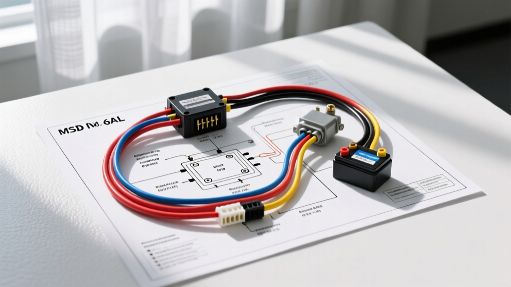
Understanding the MSD 6AL Capacitive Discharge System
Upgrading to an MSD 6AL (Part No. 6425) capacitive discharge (CD) ignition system is one of the most effective ways to eliminate misfires, improve throttle response, and ensure complete combustion in high-performance or heavily modified engines. Unlike standard inductive ignition systems that rely on the coil's dwell time to build energy, the MSD 6AL stores high voltage in large capacitors and releases it in a rapid series of sparks. However, the immense electrical current required to charge these capacitors means that a flawed installation will result in voltage drops, weak sparks, or catastrophic module failure.
This practical how-to guide breaks down the exact wiring diagram for MSD 6AL installations, detailing AWG requirements, trigger source configurations, and professional-grade routing techniques to ensure your ignition system performs flawlessly under load.
Decoding the Wiring Diagram for MSD 6AL
The MSD 6AL harness utilizes a color-coded system that separates high-amperage power circuits from low-voltage trigger signals. Misidentifying these wires is the most common cause of installation failure. Below is the master specification chart for the 6425 harness.
| Wire Color | Circuit Function | Recommended AWG | Connection Point |
|---|---|---|---|
| Heavy Red | Main Battery Power (+12V) | 8 AWG (Stranded Copper) | Direct to Battery (+) or Starter Solenoid (+) |
| Heavy Black | Main System Ground | 8 AWG (Stranded Copper) | Engine Block or Clean Chassis Ground |
| Small Red | Switched Ignition (+12V) | 16 AWG | Ignition Switch 'Run' Terminal |
| Orange | Coil Output (+) | N/A (Factory Shielded) | Ignition Coil Positive (+) Terminal |
| Black (Small) | Coil Output (-) | N/A (Factory Shielded) | Ignition Coil Negative (-) Terminal |
| White | Points/Amplifier Trigger (NC) | 18 AWG | Distributor Points or HEI Module Tach Out |
| Violet | Magnetic Pickup (+) | 18 AWG | Magnetic Distributor (+) Terminal |
| Green | Magnetic Pickup (-) | 18 AWG | Magnetic Distributor (-) Terminal |
Primary Power and Ground Circuit Requirements
The MSD 6AL can draw upwards of 15 to 20 amps continuously at high RPM, with peak transient spikes exceeding 30 amps. Relying on factory 12 AWG chassis wiring to feed the Heavy Red wire will cause severe voltage drop, starving the capacitors and resulting in a weak spark.
Power Routing (Heavy Red)
- Wire Selection: Use 8 AWG oxygen-free copper (OFC) stranded wire. Avoid Copper-Clad Aluminum (CCA) wire, which has higher resistance and degrades under engine bay heat.
- Fusing: Install a 40A inline Maxi-fuse holder within 6 inches of the battery positive terminal. This protects the harness in the event of a short circuit.
- Termination: Use adhesive-lined heat-shrink ring terminals. According to SAE J1141 electrical standards, crimped connections with environmental seals are superior to soldered joints in high-vibration automotive applications, as solder can wick into the wire strands and create brittle fracture points.
Grounding Protocol (Heavy Black)
Do not ground the MSD 6AL to the vehicle's sheet metal or a painted bracket. The ground must terminate directly on the engine block or cylinder head. Use a stainless steel star washer to bite through the metal surface, ensuring bare metal-to-metal contact. Apply a thin layer of dielectric grease over the completed terminal to prevent galvanic corrosion.
Selecting Your Trigger Source
The wiring diagram for MSD 6AL changes depending on your distributor type. The 6AL is designed to accept three distinct trigger signals, but only one trigger method should be wired at a time. Cap and isolate all unused trigger wires.
Scenario A: Breaker Points Distributor
If you are running a traditional points-style distributor, the MSD box handles the dwell and points current, saving your points from burning out.
- Connection: Connect the White wire to the negative terminal of the ignition coil (or directly to the points wire coming out of the distributor).
- Unused: Cap the Violet, Green, and Orange wires.
- Note: Ensure the factory ballast resistor wire is bypassed or removed, as the MSD requires full 12V at the coil during cranking and running.
Scenario B: Electronic Amplifier (HEI, TFI, or External Module)
For vehicles equipped with factory electronic ignition (like GM HEI or Ford TFI), you must tap into the module's output signal.
- Connection: Connect the White wire to the 'Tach Out' terminal on the HEI cap, or the negative terminal of the ignition coil if driven by an external amplifier.
- Unused: Cap the Violet, Green, and Orange wires.
Scenario C: Magnetic Pickup Distributor
For aftermarket distributors (like MSD Pro-Billet) utilizing a magnetic pickup, the trigger connection is a direct plug-and-play via the supplied 3-pin Weathertight connector.
- Connection: Violet wire to Magnetic Pickup (+), Green wire to Magnetic Pickup (-).
- Unused: Cap the White and Orange wires.
- Phase Check: If the engine backfires through the carburetor upon startup, the magnetic pickup polarity is reversed. Swap the Violet and Green wires at the distributor connector to correct the phasing.
Coil Output and High-Voltage Routing
The MSD 6AL outputs high-voltage, high-frequency pulses via the Orange (Coil +) and Black (Coil -) wires. These wires are uniquely shielded to prevent Electromagnetic Interference (EMI) and Radio Frequency Interference (RFI).
- Never Ground the Black Coil Wire: The small black wire is not a ground wire. It is the return path for the high-voltage pulse. Connecting it to the chassis will instantly destroy the MSD's internal IGBT transistors.
- Coil Selection: The 6AL requires a low-resistance ignition coil (e.g., MSD Blaster SS with 0.32 Ohms primary resistance). Using a stock coil with 1.5+ Ohms primary resistance will cause the MSD box to overheat and fail prematurely.
- Routing: Keep the Orange and Black coil wires at least 12 inches away from the trigger wires (Violet/Green/White) and any audio system wiring to prevent cross-talk and alternator whine.
Step-by-Step Installation Procedure
- Disconnect Battery: Remove the negative battery terminal to prevent accidental shorts or ECU damage.
- Mount the Module: Secure the MSD 6AL to a flat, well-ventilated surface in the engine bay or cabin. Avoid mounting near exhaust manifolds or directly on the firewall above the engine, as the heat sink relies on ambient airflow.
- Run Power and Ground: Route the 8 AWG Heavy Red and Heavy Black wires, securing them with nylon zip ties away from moving belts and sharp edges.
- Wire the Trigger: Select your trigger scenario (Points, Amplifier, or Magnetic) and make the appropriate connections using crimp butt connectors and heat shrink.
- Connect the Coil: Attach the MSD Orange wire to the Coil (+) and the MSD Black wire to the Coil (-).
- Connect Switched Power: Wire the Small Red wire to a true 12V ignition-switched source. Do not connect this to a ballast resistor wire, as voltage drop will cause the MSD to shut off under load.
- Final Check: Reconnect the battery. Turn the key to the 'Run' position (do not crank). Use a multimeter to verify 12V+ at the Small Red wire and the Heavy Red wire.
Troubleshooting Common Wiring Faults
Even with a perfect wiring diagram for MSD 6AL, environmental factors and minor errors can cause issues. Use this decision tree to diagnose problems.
| Symptom | Probable Cause | Diagnostic Fix |
|---|---|---|
| Engine cranks but has no spark | Loss of switched 12V or bad ground | Check Small Red wire for 12V during crank. Verify Heavy Black ground continuity to block. |
| Engine backfires through carburetor | Magnetic pickup polarity reversed | Swap the Violet and Green trigger wires at the distributor. |
| Alternator whine in stereo | Ground loop or EMI cross-talk | Ensure MSD ground is dedicated. Route trigger wires away from alternator and coil wires. |
| MSD Box gets excessively hot | Wrong coil or charging system overvoltage | Verify coil primary resistance is under 0.5 Ohms. Check alternator output (must be under 14.8V). |
Authoritative References
For further technical validation and advanced timing curve programming, always consult the Holley MSD 6AL Official Instruction Manual. Adherence to SAE J1141 wiring practices ensures long-term reliability of your high-performance electrical system.