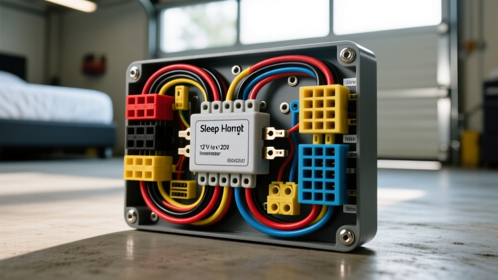
Integrating Residential Air Beds into Mobile 12V/120V Architectures
High-end Class B Sprinter conversions, Class A motorhomes, and custom expedition vehicles increasingly incorporate residential-grade furniture to maximize comfort on the road. Among the most complex of these additions is the adjustable air bed. When custom upfitters and DIY van builders search for a standard sleep number bed wiring diagram pdf, they are typically presented with residential 120V AC schematics designed for grid-tied homes. However, adapting this technology to a mobile environment requires a fundamental translation from static AC power to a dynamic 12V DC / 120V AC RV electrical architecture.
This guide provides a step-by-step troubleshooting and installation flow for integrating an air bed pump and control system into a vehicle's house battery bank, ensuring reliable inflation, preventing parasitic draws, and eliminating electromagnetic interference (EMI) with the vehicle's CAN bus systems.
Step 1: Translating the OEM Diagram for Mobile Inverter Use
The standard residential wiring schematic outlines a 120V AC power cord feeding a central control box. This box distributes low-voltage DC (typically 12V or 5V via a step-down transformer) to the handheld or wireless remote receiver, and routes 120V AC directly to the air compressor pump. The pump motor generally draws between 1.2A and 1.8A at 120V AC (144W to 216W) during active inflation.
Inverter Sizing and Waveform Requirements
While the continuous draw is under 200W, the startup surge (Locked Rotor Amperage) of the pump's induction motor can spike to 450W for a fraction of a second. Furthermore, the internal PCB of the bed's control unit is highly sensitive to dirty power.
- Waveform: You must use a Pure Sine Wave (PSW) inverter. Modified Sine Wave (MSW) inverters will cause the pump motor to overheat, buzz loudly, and eventually fail due to harmonic distortion.
- Sizing: A dedicated 400W or 600W PSW inverter is recommended. Sharing a 2000W whole-house inverter is possible but introduces unnecessary voltage drop if the bed is located far from the main inverter.
Step 2: 12V DC Feed Sizing and Overcurrent Protection
To power a dedicated 400W inverter for the bed system, we must calculate the DC amperage draw to select the correct AWG wire and overcurrent protection. Using the formula: DC Amps = (AC Watts / Inverter Efficiency) / DC Voltage.
Assuming 200W AC load, 85% inverter efficiency, and a nominal 12.5V battery bank:
200 / 0.85 = 235W DC input. 235W / 12.5V = 18.8 Amps.
DC Wiring Specification Chart
| One-Way Wire Run Distance | Recommended AWG (Stranded Copper) | Max Voltage Drop (3%) | Required Overcurrent Protection |
|---|---|---|---|
| Under 5 Feet | 6 AWG | 0.37V | 30A ANL or Class T Fuse |
| 5 to 10 Feet | 4 AWG | 0.30V | 40A ANL or Class T Fuse |
| 10 to 15 Feet | 2 AWG | 0.24V | 50A ANL or Class T Fuse |
Note: Always route the DC positive and negative cables together in the same loom or conduit to cancel the magnetic field and reduce EMI, as per SAE International Standards for automotive wiring.
Step 3: Ignition-Triggered Solenoid Integration
A critical failure mode in RV builds is leaving the bed's AC plug energized while driving. This allows the bed's internal transformer to draw a phantom load (0.5A - 1.2A DC), which can drain the house bank over a multi-day boondocking trip. To prevent this, the inverter's DC feed must be gated by an ignition-triggered solenoid.
Solenoid Pinout and Wiring Logic
Do not use a standard 40A Bosch-style automotive relay for the main DC feed. The massive inrush current required to charge the inverter's internal capacitors will weld the relay contacts shut. Instead, use a Continuous Duty Solenoid (e.g., Blue Sea 9012 or equivalent) rated for high inrush.
- Terminal A (Coil +): Connect to an ignition-switched 12V source (D+ terminal on the alternator or an upfitter ignition bus).
- Terminal B (Coil -): Connect to the chassis or house ground busbar.
- Terminal 1 (Input): Connect to the House Battery Positive Busbar (via the main Class T fuse).
- Terminal 2 (Output): Connect to the Positive input terminal of the dedicated bed inverter.
When the vehicle chassis is turned on, the solenoid closes, allowing the bed to adjust. When the ignition is off, the solenoid opens, completely isolating the bed's parasitic draw from the house bank. For detailed circuit protection guidelines, refer to the Blue Sea Systems Circuit Protection Guide.
Step-by-Step Troubleshooting Flow: Pump and Inverter Failures
When the bed fails to inflate or the remote goes dead in a mobile environment, the issue is rarely the bed itself. Use this diagnostic decision tree to isolate the fault using a digital multimeter (DMM).
| Symptom | Probable Cause | Diagnostic Step & Fix |
|---|---|---|
| Pump hums loudly but does not inflate; remote display flickers. | Modified Sine Wave (MSW) inverter is being used, causing harmonic distortion and PCB voltage sag. | Test: Measure AC output with an oscilloscope or True-RMS meter. Fix: Replace MSW inverter with a Pure Sine Wave (PSW) unit. |
| Inverter throws 'Low Voltage' fault immediately upon pump startup. | Excessive voltage drop on the 12V DC feed due to undersized wire or loose busbar crimps. | Test: Measure DC voltage at the battery, then at the inverter terminals while the pump runs. A drop >1.5V indicates bad wiring. Fix: Upgrade to 4 AWG or 2 AWG wire and re-crimp with adhesive heat shrink. |
| Bed works on shore power, but fails when running off the house battery bank. | Inverter AC transfer switch failure, or the ignition solenoid is failing to close due to a blown D+ fuse. | Test: Check for 12V at the solenoid coil trigger wire with the ignition ON. Fix: Replace the blown ignition bus fuse or repair the D+ trigger wire. |
| Remote control display is completely dead; no response from pump. | Internal 120V-to-12V step-down transformer inside the bed's control box has failed due to mobile voltage spikes. | Test: Open the OEM control box and test the DC output pins to the remote receiver. Fix: Bypass the OEM transformer and wire the remote receiver directly to a regulated 12V DC mobile fuse block. |
Chassis Grounding and EMI Suppression
In a steel or aluminum Sprinter chassis, electromagnetic interference (EMI) from the alternator and inverter can severely disrupt the low-voltage data cables connecting the bed's remote receiver to the main pump control unit. This manifests as 'ghost' inflation, where the bed randomly inflates or deflates while driving.
To resolve this, adhere to the RVIA Electrical Systems Best Practices by implementing the following:
- Ferrite Cores: Snap ferrite beads onto the low-voltage data cables near the control box to choke high-frequency alternator whine.
- Star Grounding: Do not ground the inverter to the vehicle chassis sheet metal. Run a dedicated 4 AWG ground wire directly back to the house battery negative busbar to prevent ground loops.
- AC Sub-Panel Isolation: Ensure the 120V AC receptacle powering the bed is protected by a GFCI breaker specifically rated for mobile/RV use, as standard residential GFCIs are prone to nuisance tripping from the harmonic noise of mobile inverters.
By treating the bed not as a static appliance, but as a dynamic load interacting with a mobile DC microgrid, you ensure reliable operation whether parked at a campground or boondocking off-grid.