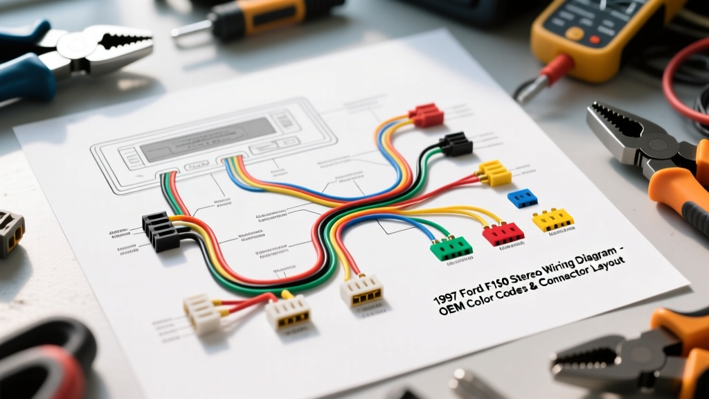
Introduction to the 1997 F-150 Audio Architecture
Upgrading the head unit in a 10th-generation 1997 Ford F-150 requires more than just matching wire colors. As the first year of the redesigned PN96 platform, the 1997 F-150 introduced a new Central Junction Box (CJB) and updated interior lighting circuits that interact directly with the factory stereo harness. Whether you are swapping a failing OEM cassette deck for a modern Bluetooth receiver or installing a high-power aftermarket amplifier, interpreting the 1997 Ford F150 stereo wiring diagram correctly is critical to avoid blowing the interior lighting fuse or damaging the new head unit.
This guide approaches the installation from a Cost & Tool Requirements Analysis perspective. We will break down the exact tools required, the true cost of harness adapters versus hardwiring, and the specific OEM wire color codes and AWG ratings you need to execute a professional-grade installation.
Essential Tools & Cost Breakdown for the 1997 F-150
Before you pull the dash bezel, you must assemble the right toolkit. The 1997 F-150 dash utilizes a combination of 7mm bolts and hidden push-clips to secure the radio chassis. Attempting to pry the bezel without proper trim tools will result in cracked ABS plastic, turning a $100 stereo swap into a $300 dash replacement.
| Tool / Supply | Specification / Use Case | Est. Cost |
|---|---|---|
| Trim Panel Removal Kit | Nylon pry tools for dash bezel and 7mm socket for radio brackets | $12 - $25 |
| Digital Multimeter | Required to verify Switched 12V and Ground continuity (e.g., AstroAI or Fluke) | $15 - $60 |
| Ratcheting Crimp Tool | For 22-16 AWG insulated butt connectors (superior to solder for automotive vibration) | $25 - $45 |
| Wire Strippers | Precision strippers for 18 AWG speaker wire and 14 AWG power wire | $15 - $30 |
| Electrical Tape / Heat Shrink | Adhesive-lined heat shrink (3:1 ratio) for moisture and vibration resistance | $10 - $20 |
| Wiring Harness Adapter | Metra 70-5511 or Scosche F02B (Plug-and-play solution) | $8 - $15 |
Total Baseline Tool & Supply Cost: $85 - $195 (assuming you do not already own a multimeter and crimpers).
Decoding the 1997 Ford F150 Stereo Wiring Diagram
The base audio system in the 1997 Ford F-150 utilizes a standard Ford 16-pin connector, physically split into two 8-pin blocks. Block A handles power, ground, and illumination, while Block B handles the four-channel speaker outputs. The OEM wiring uses 18 AWG stranded copper for speaker runs and 14 AWG for the constant 12V memory circuit.
Block A: Power, Ground, and Accessory Circuits
| Wire Color (OEM) | Function | AWG Rating | Testing Notes |
|---|---|---|---|
| Yellow | Constant 12V+ (Battery / Memory) | 14 AWG | Hot at all times. Tied directly to the battery via the CJB. |
| Light Green / Purple | Switched 12V+ (Ignition / Accessory) | 16 AWG | Only hot when the key is in ACC or RUN. Use a multimeter to verify. |
| Black | Chassis Ground | 14 AWG | Must show less than 0.1 ohms of resistance to bare chassis metal. |
| Orange / Black | Illumination (Headlight Switch) | 18 AWG | Receives 12V when parking lights or headlights are turned on. |
| Orange | Dimmer Circuit | 18 AWG | Variable voltage (0V to 12V) based on the dash dimmer thumbwheel. |
Block B: Speaker Output Color Codes
Ford standardized its speaker wire colors in the mid-90s to match the EIA (Electronic Industries Alliance) aftermarket standard, making harness adapters highly reliable for the 1997 model year.
- Front Left: White (Positive) / White with Black Stripe (Negative)
- Front Right: Gray (Positive) / Gray with Black Stripe (Negative)
- Rear Left: Green (Positive) / Green with Black Stripe (Negative)
- Rear Right: Purple (Positive) / Purple with Black Stripe (Negative)
Warning: Never ground the negative speaker wires to the chassis. The 1997 F-150 factory radio, and most modern aftermarket head units, utilize a floating ground BTL (Bridge-Tied Load) amplifier IC. Grounding a negative speaker wire will instantly short the internal amplifier chip, permanently destroying the head unit.
Handling the Premium Audio System (External Amplifier)
If your 1997 F-150 is an XLT or Eddie Bauer edition equipped with the factory premium sound system (often branded as Mach 460 or simply 'Premium Audio'), the wiring diagram changes significantly. The premium system features a factory external amplifier mounted behind the dash or under the rear seat in SuperCab models.
The standard speaker wires in the 16-pin harness do not carry amplified speaker-level signals; instead, they carry low-level pre-out signals, and the harness includes a Blue/White wire for the amplifier turn-on trigger. If you use a standard 70-5511 adapter on a premium system, you will get no sound. You must purchase a premium bypass harness (such as the Metra 70-5519 or an Axxess XFD-17) which costs approximately $25 to $40. This harness includes the necessary resistors and RCA pigtails to convert the high-level outputs of your new stereo back to low-level signals for the factory amp, or allows you to bypass the factory amp entirely by running new 16 AWG speaker wire directly to the door panels.
Cost Analysis: Harness Adapters vs. Hardwiring
When analyzing the cost of your 1997 Ford F150 stereo wiring diagram implementation, you have two choices: hardwiring or using an adapter.
The Hardwiring Approach (Not Recommended)
Hardwiring involves cutting the OEM Ford plug off and soldering or crimping your new stereo's pigtail directly to the truck's wires. While the raw material cost is low (about $4 for a box of 18-22 AWG heat-shrink butt connectors), the hidden costs are severe. You lose the ability to revert to the factory radio, which hurts the truck's resale value. Furthermore, cutting into the OEM 14 AWG constant power wire limits your future upgrade path. If you later add a 500W subwoofer amplifier, you cannot safely pull the remote turn-on signal or memory wire from a spliced, degraded OEM connection.
The Adapter Harness Approach (Highly Recommended)
Purchasing a Metra 70-5511 adapter harness costs roughly $12. You wire the adapter to your new stereo's pigtail on your workbench using proper ratcheting crimpers, then simply plug the adapter into the Ford OEM connector. This preserves the truck's OEM wiring integrity, prevents the voiding of any remaining legacy electrical warranties, and ensures that if the new head unit fails, you can swap it out in 5 minutes. The $8 premium for the adapter pays for itself immediately in labor savings and risk mitigation.
Real-World Troubleshooting & Failure Modes
When working with the 1997 F-150 electrical system, installers frequently encounter specific failure modes related to the illumination and dimmer circuits.
Blown Interior Lighting Fuse (CJB Fuse #14)
The most common mistake when wiring the 1997 Ford F150 stereo wiring diagram is improperly capping the Orange/Black (Illumination) and Orange (Dimmer) wires. If the Orange/Black wire is accidentally pinched behind the metal radio chassis and shorts to ground, it will immediately blow Fuse #14 in the Central Junction Box (located under the dash on the driver's side). This fuse controls the interior dome lights, the bed light, and the radio illumination. If your new stereo works but your dome lights are dead, check this 15-amp mini fuse.
Head Unit Losing Memory (Presets and Clock Reset)
If your new stereo loses its memory every time you turn off the truck, the Yellow (Constant 12V) and Light Green/Purple (Switched 12V) wires have likely been swapped. Use your digital multimeter to test the OEM Ford harness before plugging in the adapter. The Yellow wire must read 12.4V with the truck off and the key out of the ignition. The Light Green/Purple wire must read 0V with the key off, and 12.4V with the key in the ACC position. For more detailed testing procedures, refer to the Haynes Automotive Electrical Manual.
Authoritative References
To ensure accuracy and safety during your installation, always cross-reference your specific truck's VIN and trim level with manufacturer documentation. The following resources were utilized to compile the pinouts, AWG specifications, and CJB fuse data for this guide:
- Metra Electronics Vehicle Fitment Database - For OEM harness part numbers and premium audio bypass configurations.
- Haynes Manuals: Ford F-150 (1997-2003) Repair Guide - For Central Junction Box fuse layouts and chassis grounding points.
- Crutchfield Car Audio Installation Guides - For EIA standard speaker wire color codes and dash kit compatibility.