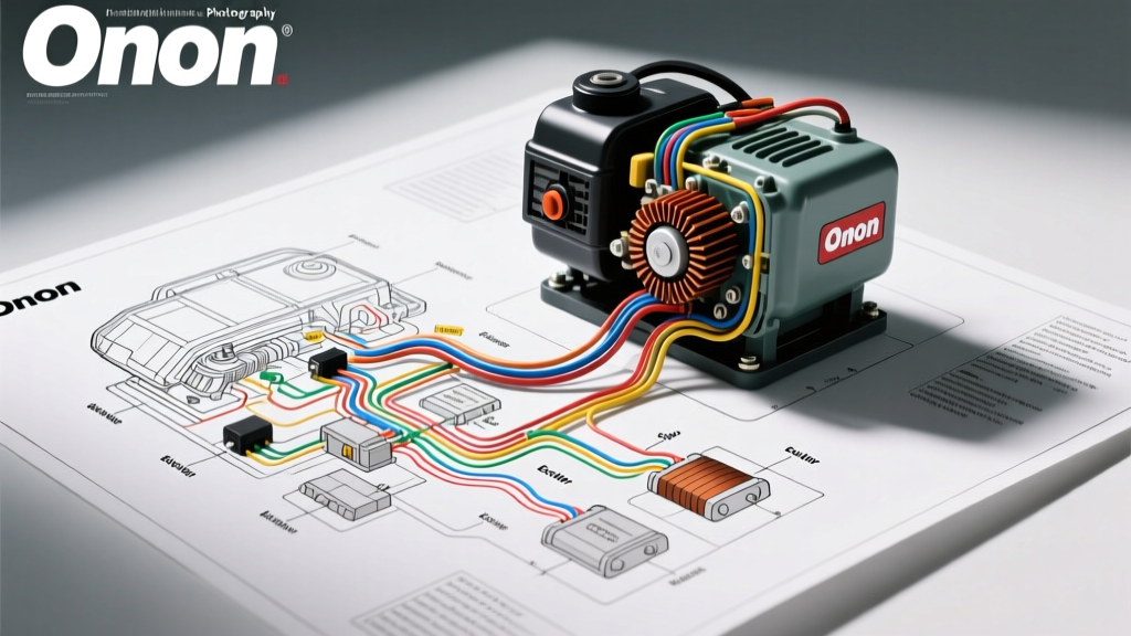
Understanding the Onan Generator Wiring Schematic
For RV technicians, fleet mechanics, and DIY motorhome owners, the Onan generator wiring schematic is the ultimate roadmap for diagnosing electrical faults. Whether you are working on a 4000 MicroQuiet (KY), a 5500 Marquis Gold, or a larger 7500/10000 series commercial RV unit, the fundamental architecture of the electrical generation system remains remarkably consistent. Unlike standard automotive alternators that rely on the vehicle's engine to spin the rotor, an Onan RV generator utilizes a dedicated internal combustion engine coupled directly to a revolving field (rotor) and a stationary armature (stator).
A complete wiring diagram walkthrough requires breaking the schematic down into three distinct subsystems: the DC cranking and control circuit, the AC exciter and main stator windings, and the voltage regulator (VR) field circuit. By tracing the wire color codes, AWG specifications, and connector pinouts outlined below, you can systematically isolate no-start conditions, low-voltage AC output, and complete generator failures.
1. The DC Cranking and Control Circuit
The DC side of the schematic governs the 12-volt supply required to crank the generator engine and power the control board logic. According to SAE J1127 standards for battery cables, the main positive and negative battery leads must be sized appropriately to handle the high inrush current of the starter motor—typically 2 AWG or 4 AWG stranded copper, depending on the cable run length from the coach battery bank to the generator compartment.
Starter Solenoid (K1) and Ignition Logic
When you press the 'Start' button on the RV dash or the generator control panel, a 12V signal is sent to the control board. The board then grounds the K1 start solenoid coil. The heavy-duty contacts inside K1 close, routing 12V B+ directly to the starter motor.
- Main B+ Supply: 2 AWG Red wire from the coach battery positive terminal to the K1 solenoid battery lug.
- Control Wire: 14 AWG Red/White wire from the K1 ignition terminal to the starter motor terminal.
- Ground Path: 2 AWG Black wire from the engine block to the chassis ground bus bar.
2. AC Generation: Exciter and Main Stator Windings
The heart of the Onan generator wiring schematic is the alternator end, which houses the stator (stationary windings) and the rotor (revolving field). Onan utilizes a brushless exciter system on many of its larger models, while smaller units like the 4000 MicroQuiet use a brushed slip-ring design. For this walkthrough, we will focus on the ubiquitous brushed stator/rotor configuration found in the 4kW to 7kW RV models.
Main Stator Output (B1-B4)
The main stator windings produce the 120V/240V AC power that ultimately feeds the RV's transfer switch and breaker panel. The schematic identifies these leads as B1, B2, B3, and B4.
- B1 & B2 (Leg 1): Typically Black and Black/White 10 AWG wires. These supply the first 120V leg.
- B3 & B4 (Leg 2): Typically Red and Red/White 10 AWG wires. These supply the second 120V leg (which combines with Leg 1 to provide 240V for large motorhomes).
Exciter Windings (E1-E3)
Before the main stator can produce usable AC power, the voltage regulator needs a reference voltage and a power source to operate. This is provided by the exciter windings, labeled E1, E2, and E3 on the schematic. These are typically 14 AWG Yellow, Yellow/Black, and Yellow/White wires. As residual magnetism in the rotor cuts across the exciter windings during cranking, a small AC voltage is generated. This AC voltage is rectified to DC by the voltage regulator to power its internal logic and to feed the rotor's field windings.
3. Voltage Regulator and Field Circuit (F1-F2)
The Voltage Regulator (VR) is the brain of the AC generation side. It monitors the AC output from the main stator and adjusts the DC current sent to the rotor to maintain a steady 120V/60Hz output. The connection between the VR and the rotor is made via two carbon brushes riding on copper slip rings.
The schematic labels these field connections as F1 and F2.
- F1 (Positive Field): 16 AWG Blue wire.
- F2 (Negative Field): 16 AWG Blue/White wire.
Terminal and Wire Color Reference Chart
Use the following reference chart to quickly identify wires when tracing the Onan generator wiring schematic on 4000-5500 watt RV units.
| Terminal ID | Wire Color | AWG Size | Circuit Function |
|---|---|---|---|
| B+ | Red | 2 AWG | Main 12V Battery Positive to K1 Solenoid |
| GND | Black | 2 AWG | Engine Block to Chassis Ground |
| B1 | Black | 10 AWG | Main Stator Output Leg 1 (120V) |
| B2 | Black/White | 10 AWG | Main Stator Output Leg 1 Return |
| B3 | Red | 10 AWG | Main Stator Output Leg 2 (120V) |
| B4 | Red/White | 10 AWG | Main Stator Output Leg 2 Return |
| E1, E2, E3 | Yellow variants | 14 AWG | Exciter Stator AC Input to Voltage Regulator |
| F1 | Blue | 16 AWG | Positive DC Field to Rotor Brush |
| F2 | Blue/White | 16 AWG | Negative DC Field to Rotor Brush |
P1 Control Board Connector Pinout Walkthrough
The P1 connector is the primary interface between the RV's chassis wiring and the Onan generator control board. When diagnosing remote start failures or shutdown faults, verifying the pinout at P1 is critical. Based on RVDA technical guidelines and OEM schematics, the standard 12-pin P1 connector operates as follows:
- Pin 1 (Ground): 14 AWG Black. Must have continuity to the engine block.
- Pin 2 (12V B+ Constant): 14 AWG Red. Provides constant battery voltage to the board's memory and standby circuits.
- Pin 3 (Ignition/Run): 14 AWG Red/White. Receives 12V when the RV dash ignition switch is in the 'Run' position.
- Pin 4 (Remote Start): 14 AWG Yellow. Momentary ground signal from the RV dash start switch.
- Pin 5 (Remote Stop): 14 AWG Yellow/Black. Momentary ground signal from the RV dash stop switch.
- Pin 6 (Pre-heat): 14 AWG Green. Activates the glow plugs or intake heater on diesel Onan models.
- Pin 11 (AC Sense): 14 AWG White. Routes 120V AC from the main breaker back to the control board so it can verify power generation before engaging the main run relay.
Troubleshooting Workflow: Tracing a No-AC-Output Fault
When the generator engine runs perfectly but produces zero AC voltage at the coach breakers, the wiring schematic provides a logical decision tree for isolation.
Step 1: Verify Exciter Output
Disconnect the VR harness. Set your multimeter to AC Volts. Crank the engine and measure across the E1 and E2 terminals. You should see 20-30V AC. If you read 0V AC, the exciter winding is open, or the rotor has lost its residual magnetism.
Step 2: Flashing the Field
If residual magnetism is lost (common if the RV has sat for months), the schematic shows that the F1 and F2 terminals can be manually energized. With the engine OFF, apply 12V DC from a drill battery directly to the F1 (Blue) and F2 (Blue/White) wires at the brush block for 3 seconds. This 'flashes the field,' restoring the magnetic pole. Start the generator; AC output should immediately return to 120V.
Step 3: Inspect the Slip Rings and Brushes
If flashing the field fails, remove the rear bearing housing to inspect the slip rings. The schematic relies on a solid mechanical connection here. If the copper rings are black or pitted, clean them with a Scotch-Brite pad (never sandpaper, which leaves conductive copper dust that can short the windings). Measure the brush length; if they are shorter than 0.5 inches, replace the brush block assembly.
Step 4: Voltage Regulator Bench Test
If the stator, exciter, and rotor all test within OEM specifications, the wiring schematic isolates the Voltage Regulator as the final point of failure. The VR is a solid-state potted module and cannot be repaired. If the F1-F2 output from the VR reads 0V DC while the engine is cranking (and exciter input is present), replace the VR unit, ensuring you apply dielectric grease to the multi-pin connector to prevent moisture ingress common in RV underbelly installations.