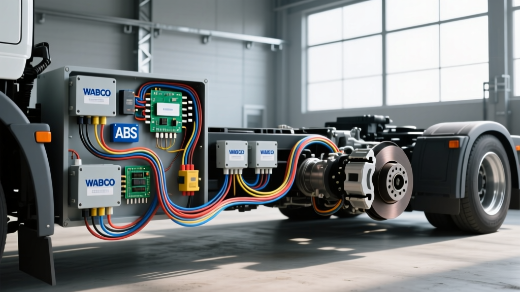
Understanding the WABCO ABS Wiring Diagram Architecture
Diagnosing anti-lock braking system faults on heavy-duty commercial trucks, trailers, and European light-commercial vans requires a methodical approach. The WABCO ABS wiring diagram dictates the flow of power, ground, wheel speed sensor (WSS) telemetry, and modulator valve actuation signals. Unlike standard passenger vehicle ABS, WABCO systems—particularly the Generation 4 and Gen 7 Trailer ABS platforms—operate in harsh, high-vibration environments where harness chafing, ISO 7638 connector corrosion, and shield degradation are the primary culprits behind phantom ABS warning lamps.
This step-by-step troubleshooting flow is engineered for diesel technicians and advanced DIYers. By following the electrical decision tree below, you can isolate open circuits, short-to-ground faults, and erratic AC signal dropouts without immediately resorting to expensive proprietary scan tools.
Core WABCO ECU Pinout and Wire Specification Chart
Before initiating the diagnostic flow, verify your harness against the standard WABCO 12-pin ECU connector layout. Note that specific wire colors may vary slightly depending on the OEM harness manufacturer (e.g., Freightliner vs. Volvo), but the AWG gauge and circuit functions remain consistent across the WABCO Gen 4 architecture.
| Pin | Circuit Function | Wire Color (Typical) | AWG Size | Notes / Tolerance |
|---|---|---|---|---|
| 1 | Constant Battery Power (Stop Light) | Red | 10 AWG | Fused at 30A; Must have < 0.2V drop under load |
| 2 | Ignition / Run Power | Black | 12 AWG | Energizes ECU logic board |
| 3 | Chassis Ground | White | 10 AWG | Star-washered to clean frame rail |
| 4 | Left WSS Signal (+) | Green | 18 AWG Shielded | Twisted pair; 1100-1300 Ohms |
| 5 | Left WSS Signal (-) | Yellow | 18 AWG Shielded | Shield drain wire grounded at ECU only |
| 6 | Right WSS Signal (+) | Gray | 18 AWG Shielded | Twisted pair; 1100-1300 Ohms |
| 7 | Right WSS Signal (-) | Brown | 18 AWG Shielded | Inspect for axle-wrap chafing |
| 8 | Modulator Valve 1 (Inlet/Outlet) | Blue | 14 AWG | PWM controlled; 2.0 - 4.0 Ohms |
| 9 | Modulator Valve 2 (Inlet/Outlet) | Orange | 14 AWG | PWM controlled; 2.0 - 4.0 Ohms |
| 10 | PLC / CAN High (Data Link) | Purple | 18 AWG | SAE J2497 Trailer Comms |
| 11 | PLC / CAN Low (Data Link) | Pink | 18 AWG | Verify 60 Ohms termination |
| 12 | ABS Warning Lamp Output | Light Green | 16 AWG | Switched ground to dash indicator |
Step-by-Step WABCO ABS Troubleshooting Flow
Step 1: Verify ECU Power and Ground Integrity
The most common cause of a completely dead WABCO ABS module is a voltage drop on the primary power or ground circuits, often misdiagnosed as a failed ECU. The ABS module requires a stable voltage supply to initialize its internal solenoid drivers and run self-checks upon key-on.
- Test 1A (Constant Power): Set your digital multimeter (DMM) to DC Volts. Back-probe Pin 1 (Red) and Pin 3 (White/Ground). You must read battery voltage (12.4V - 14.2V for 12V systems, or 24.8V - 28.4V for 24V systems). If voltage is below 11.5V, perform a voltage drop test across the 30A ABS fuse and the stop-light relay.
- Test 1B (Ground Circuit): Switch the DMM to Ohms. Measure resistance between Pin 3 and a known good, unpainted chassis ground. The reading must be less than 0.5 Ohms. If resistance is higher, remove the ground stud, clean the frame rail with a wire wheel, and reinstall using a star washer to bite through the anti-corrosion coating.
Step 2: Wheel Speed Sensor (WSS) Circuit Diagnostics
WABCO systems utilize passive magnetic induction sensors (on older Gen 3/4 systems) or active Hall-effect sensors (on newer Gen 7 systems). For the standard passive WSS, the ECU monitors both the static resistance of the coil and the dynamic AC millivolt output generated by the toothed exciter ring.
- Test 2A (Static Resistance): Disconnect the ECU harness. Set the DMM to Ohms. Measure across Pin 4 and Pin 5 (Left WSS), then Pin 6 and Pin 7 (Right WSS). The specification for a standard WABCO passive sensor is 1100 to 1300 Ohms at room temperature. An infinite reading (OL) indicates an open coil or severed harness. A reading near 0 Ohms indicates a short.
- Test 2B (Insulation to Ground): Measure resistance from Pin 4 to Chassis Ground, and Pin 5 to Chassis Ground. Both must read OL (Infinite). Any measurable resistance indicates the 18 AWG shielded wiring has chafed against the axle tube or suspension bracket, allowing moisture to short the signal to ground.
- Test 2C (Dynamic AC Output): Reconnect the ECU, back-probe the sensor pins, and set the DMM to AC Millivolts (mV). Safely raise the axle and rotate the wheel hub by hand at approximately 30 RPM. The DMM should register a minimum of 100 mV AC. A low reading indicates excessive air gap (sensor pushed back in its bore) or a damaged exciter ring with missing teeth.
- Gen 7 Active Sensor Note: Newer WABCO Generation 7 systems utilize active Hall-effect sensors requiring a 12V or 24V excitation voltage from the ECU. A static Ohms check will yield a high impedance reading or diode-drop behavior. Instead, back-probe the signal wire with the ignition ON and measure a square wave DC voltage or frequency output using a DMM with a Hz setting or an oscilloscope.
Step 3: Modulator Valve Actuation Testing
The WABCO ABS modulator valve contains internal inlet and outlet solenoids that rapidly cycle to modulate brake chamber air pressure. These solenoids are driven by Pulse Width Modulation (PWM) signals from the ECU.
- Test 3A (Solenoid Resistance): With the harness disconnected, measure the resistance across the modulator valve pins at the ECU connector (Pins 8 and 9 relative to their respective grounds/returns). Expect a reading between 2.0 and 4.0 Ohms. Because these are low-resistance circuits, use a DMM with a relative (zero) function to subtract test lead resistance.
- Test 3B (Actuation Click Test): Apply a momentary 12V jumper from the battery to the modulator valve pins directly at the valve connector. You should hear a distinct, sharp metallic click. A dull thud or no sound indicates a seized solenoid plunger or internal moisture corrosion, requiring valve replacement.
- Test 3C (Dynamic PWM Scope Test): When testing the PWM signal dynamically with an oscilloscope, the ECU will typically command the inlet solenoid at a base frequency of 100 Hz to 200 Hz, varying the duty cycle from 0% to 100% to precisely feather the air pressure. A flatline on the scope trace during a panic-stop simulation indicates a failed internal H-bridge driver within the WABCO ECU.
Step 4: Data Link and Warning Lamp Verification
Modern WABCO trailer ABS systems communicate with the tractor via Power Line Carrier (PLC) technology over the blue auxiliary circuit, or via standard CAN bus in European applications (ISO 11992).
- Test 4A (Warning Lamp Circuit): The ABS lamp (Pin 12) is typically a switched ground. With the ignition ON and engine OFF, the ECU grounds this circuit to illuminate the dash lamp for 3 seconds. Use a test light connected to 12V positive; probe Pin 12. The light should illuminate. If it does not, check for a burned-out dash bulb or a broken 16 AWG pink wire in the cab harness.
- Test 4B (PLC/CAN Termination): If the tractor is not recognizing the trailer ABS status, check the data link termination. With all power OFF, measure resistance across the CAN High and CAN Low pins at the diagnostic port. You must read 60 Ohms (indicating two 120 Ohm terminating resistors in parallel). A reading of 120 Ohms means one resistor is missing or a wire is broken in the harness.
Common Real-World WABCO Wiring Failure Modes
Based on field data from commercial fleet maintenance, the following physical wiring faults account for over 80% of WABCO ABS diagnostic trouble codes (DTCs):
- The Axle-Wrap Chafe: On trailers with air-ride suspensions, the WSS wiring harness often lacks enough slack. Over thousands of articulation cycles, the 18 AWG shielded cable rubs against the sharp edge of the axle torque rod bracket, eventually grounding the Green/Yellow signal wires. Fix: Reroute using split-loom and Adel clamps with rubber cushions.
- ISO 7638 Connector Corrosion: The 7-pin/5-pin combo connector used for tractor-trailer ABS power and data is highly exposed to road salt. Galvanic corrosion between the copper pins and aluminum housing creates a high-resistance voltage drop on Pin 1 and 2. Fix: Clean with electrical contact cleaner and apply dielectric grease; never use petroleum jelly.
- Shield Drain Wire Ground Loops: The foil shield on the WSS twisted pair must only be grounded at the ECU end. If a previous technician grounded the shield at the sensor pigtail, electromagnetic interference (EMI) from the alternator or nearby high-current starter cables will induce false AC voltage spikes, causing the ABS to activate erratically on dry pavement.
Authoritative References and Standards
- SAE J2497 - Standard for Trailer ABS Power Line Carrier (PLC) Messaging and Electrical Requirements.
- WABCO Trailer ABS Technical Service Documentation - Official Gen 4 and Gen 7 ECU Pinouts and Diagnostic Flowcharts.
- Commercial Vehicle Repair Network (CVRN) - Best practices for heavy-duty commercial braking system electrical diagnostics.