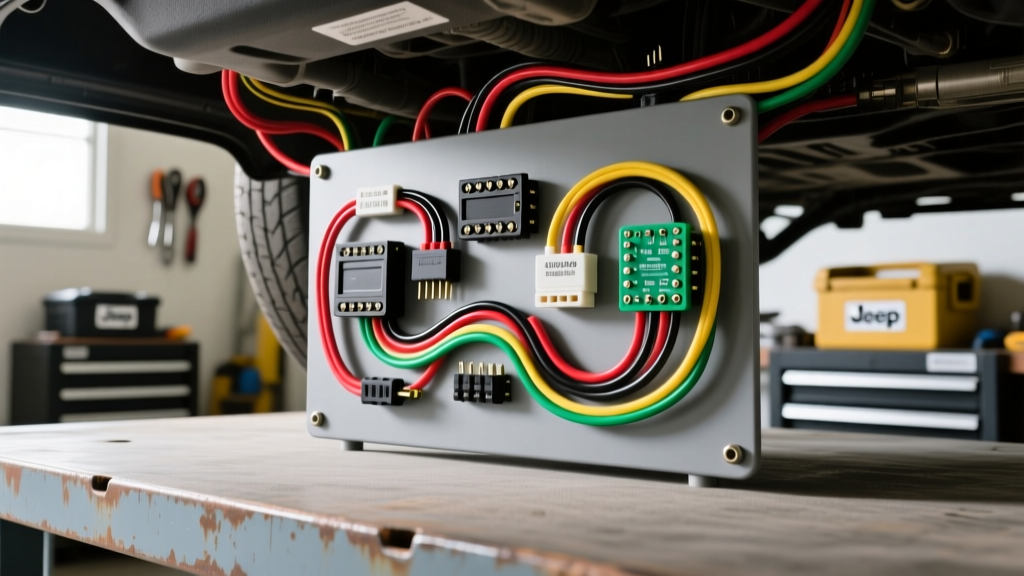
The 2013 Jeep Wrangler (JK) Audio Architecture
Upgrading the factory stereo in a 2013 Jeep Wrangler (JK generation) is one of the most popular modification projects for off-road enthusiasts and daily drivers alike. However, the 2013 model year presents unique electrical challenges compared to older vehicles. The 2013 JK utilizes a Controller Area Network (CAN-bus) system managed by the Totally Integrated Power Module (TIPM) to handle accessory power states, steering wheel controls, and vehicle data. Unlike legacy vehicles, there is no traditional 12V switched accessory wire at the back of the radio harness. Instead, the radio requests a wake-up signal via the data network.
To successfully install an aftermarket double-DIN head unit, add a DSP, or integrate a high-output amplifier, you must understand the OEM pinouts, bypass the factory Alpine amplifier (if equipped), and properly interface with the CAN network. This guide provides the definitive 2013 Jeep Wrangler radio wiring diagram and technical specifications required for a flawless installation.
Main 22-Pin Radio Harness Pinout Diagram
The base audio system and the standard 430N/730N Uconnect systems in the 2013 Wrangler utilize a primary 22-pin connector (C1) for power, ground, data, and front/rear speaker outputs. Below is the exact OEM pin configuration and wire color code reference.
| Pin | Wire Color | Function | Specification / Notes |
|---|---|---|---|
| 1 | Yellow | 12V Battery Constant (B+) | Fused via TIPM. 18 AWG. Memory and amplifier remote turn-on source. |
| 2 | Pink/White | CAN-Bus High (CAN-H) | Twisted pair data line. Requires CAN interface for aftermarket radio. |
| 3 | Pink/Black | CAN-Bus Low (CAN-L) | Twisted pair data line. Do not separate from CAN-H for more than 2 inches. |
| 9 | Dark Green | Left Front Speaker (+) | 18 AWG. Standard Chrysler speaker polarity. |
| 10 | Dark Green/Orange | Left Front Speaker (-) | 18 AWG. Returns to head unit or factory amp. |
| 13 | Black | Chassis Ground (GND) | 16 AWG. Must be secured to bare metal if extending. |
| 15 | White | Right Front Speaker (+) | 18 AWG. |
| 16 | White/Black | Right Front Speaker (-) | 18 AWG. |
| 17 | Brown | Left Rear Speaker (+) | 18 AWG. Routes to rear sound bar or subwoofer enclosure. |
| 18 | Brown/Orange | Left Rear Speaker (-) | 18 AWG. |
| 19 | Violet | Right Rear Speaker (+) | 18 AWG. |
| 20 | Violet/Orange | Right Rear Speaker (-) | 18 AWG. |
| 22 | N/A | Accessory Wake-Up | Handled via CAN-Bus. No physical 12V switched wire present. |
Source reference: Pinout data verified against Metra Electronics Vehicle Fitment Database and Chrysler JK service schematics.
Solving the CAN-Bus and Accessory Power Challenge
Because the 2013 Wrangler lacks a 12V accessory (red) wire at the head unit, you cannot simply splice an aftermarket radio's red wire to a fuse tap and expect seamless operation without triggering TIPM fault codes or experiencing battery drain. The factory radio communicates with the TIPM to confirm when the ignition cylinder is in the ACC or RUN position.
Required Interface Modules
To retain steering wheel controls (SWC), generate a 12V accessory turn-on signal for the aftermarket radio, and maintain vehicle data integrity, you must use a CAN-bus decoding module. Industry-standard solutions include:
- iDatalink Maestro RR / RR2: Provides a comprehensive data bridge, allowing the aftermarket screen to display vehicle gauges, TPMS, and door-ajar warnings. Requires a firmware-flashed head unit (e.g., Kenwood eXcelon or Alpine Halo).
- PAC RP4-CH11: A robust, standalone interface that generates the 12V accessory output and decodes SWC signals. Refer to the PAC Audio CAN-Bus Integration Guides for specific dip-switch configurations for the 2013 JK.
Wiring the Data Lines: The CAN-H (Pink/White) and CAN-L (Pink/Black) wires must be spliced using T-taps or, preferably, by cutting and soldering with heat shrink. Maintain the twisted-pair geometry as much as possible to prevent electromagnetic interference (EMI) from the ignition coils, which can cause the radio to randomly reboot or the TIPM to throw U-code network faults.
Bypassing the Factory Alpine Amplifier
If your 2013 Wrangler is equipped with the premium Alpine audio system (often paired with the 430NAV or 730NAV Uconnect), the speaker wires at the back of the radio do not go directly to the speakers. They send low-level differential signals to a factory amplifier located in the passenger-side footwell, behind the kick panel and carpet.
The Bypass Procedure
When installing an aftermarket head unit with built-in 50W x 4 RMS amplification, or when adding a dedicated line output converter (LOC) for a subwoofer, you must bypass the factory Alpine amp.
- Remove the Passenger Kick Panel: Pull back the carpet and remove the plastic trim to expose the silver-finned Alpine amplifier.
- Disconnect the 10-Pin and 14-Pin Connectors: The 14-pin connector holds the speaker outputs; the 10-pin holds power, ground, and the amp turn-on signal.
- Run New Speaker Wire: The most reliable method is to run new 16 AWG or 14 AWG OFC (Oxygen-Free Copper) speaker wire from the new head unit's harness directly to the factory speaker locations (dash and soundbar). Routing wire through the JK's rubber door boots requires a stiff wire fish-tape and silicone dielectric grease to prevent tearing the weather seals.
- Alternative (LOC Method): If you are keeping the factory speaker wiring, you must use a specialized line output converter (like the AudioControl LC2i) tapped into the factory amp's input wires at the head unit, as the signal is already low-level but requires differential summing.
Amplifier Power Routing and AWG Specifications
For modification projects involving a mono-block subwoofer amplifier or a 5-channel system amplifier, proper power wire routing is critical to prevent voltage drop and alternator whine. The 2013 JK's firewall offers a specific pass-through point that avoids the airbags and main TIPM harnesses.
| System Component | Recommended AWG | Wire Type | Routing / Fuse Spec |
|---|---|---|---|
| Main Amp Power (Up to 800W) | 4 AWG | OFC Copper | Route through firewall grommet behind glovebox. ANL Fuse within 18 inches of battery. |
| Main Amp Power (800W - 1500W) | 1/0 AWG | OFC Copper | Requires upgrading the main battery terminals. Use a distribution block under the hood. |
| Chassis Ground | Match Power | OFC Copper | Must terminate to bare, sanded metal on the seatbelt tower or rear wheel well. Max 18" length. |
| Remote Turn-On | 18 AWG | Primary Wire | Connect to the blue/white wire from the CAN-bus interface module. |
Firewall Pass-Through: The safest route for 4 AWG power wire is through the large rubber grommet located on the passenger side of the firewall, directly behind the glove box assembly. Carefully pierce the rubber with a dedicated grommet tool or a Phillips screwdriver, feed the wire, and seal the puncture with RTV silicone to prevent water intrusion into the cabin.
Troubleshooting Common JK Audio Modifications
Even with the correct 2013 Jeep Wrangler radio wiring diagram, installers frequently encounter specific electrical anomalies native to the JK platform. Use this decision tree to diagnose your issues:
Symptom: Radio Turns On, But Speakers Pop Loudly on Engine Shutdown
- Cause: The TIPM maintains power to the CAN network for up to 10 minutes after the ignition is turned off (the "RAP" or Retained Accessory Power state). If your aftermarket amplifier remote turn-on wire is tied to a fuse tap that stays hot, the amp remains on while the head unit cuts the audio signal, causing a DC offset pop.
- Fix: Ensure the amplifier remote turn-on (blue/white) is wired exclusively to the accessory output generated by your CAN-bus interface module, not a constant 12V source.
Symptom: Head Unit Randomly Reboots While Driving Off-Road
- Cause: Voltage drop across a poor chassis ground or CAN-bus EMI interference from the high-voltage ignition coils firing under heavy load.
- Fix: Verify the black ground wire at the 22-pin harness is under 0.05 ohms of resistance to the battery negative terminal. Ensure the CAN-H and CAN-L wires are not routed parallel to the ignition coil harness or the blower motor power wires.
Symptom: Steering Wheel Volume Buttons Work, But 'Seek/Track' Does Not
- Cause: The 2013 Wrangler uses a resistive ladder network for SWC, but the CAN interface module dip-switches or firmware are mapped to the pre-2011 Chrysler protocol.
- Fix: Consult the Crutchfield Jeep Wrangler Integration Guide or your specific interface module manual to update the resistance mapping or flash the module firmware to the 2011-2018 JK CAN protocol.
By adhering to these OEM pinouts, respecting the CAN-bus architecture, and utilizing proper AWG wiring standards, your 2013 Jeep Wrangler audio upgrade will deliver reliable, high-fidelity performance on the trail and the highway.