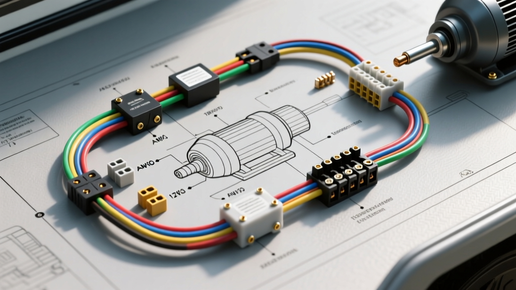
Introduction to Mobile Submersible Pump Architecture
When engineering a 12V DC electrical system for Class B/C RVs, Sprinter conversions, or overland expedition trucks, fluid management is critical. While residential applications rely on 120V/240V AC well pumps, mobile platforms require specialized 12V DC solutions. This technical reference provides the definitive wiring diagram for submersible pump installations in automotive and recreational vehicle environments. Whether you are wiring a drop-in submersible fresh water pump for a custom poly tank or a high-amperage submersible macerator pump for black water waste management, understanding AWG sizing, voltage drop mitigation, and IP68-rated connection protocols is mandatory for system reliability.
Unlike standard inline diaphragm pumps mounted on a chassis bulkhead, submersible pumps operate entirely inside the fluid reservoir. This provides superior cooling and eliminates cavitation issues, but it introduces severe environmental challenges for the electrical connections. The wiring must withstand constant immersion, chemical exposure (in grey/black tanks), and the mechanical vibration inherent to off-road vehicle platforms.
Primary Wiring Diagram: 12V Submersible Fresh Water Pump
For overland rigs utilizing auxiliary water cells, a 12V submersible water pump (typically rated between 3.0 and 5.5 GPM) is the standard for delivering pressurized water to the vehicle's plumbing manifold. These pumps generally draw between 7A and 10A under load. Because they are located inside the water tank, the wire exit gland is the most critical point of failure.
Component Specifications and Wire Routing
- Power Source: 12V DC House Battery Bank (Lithium LiFePO4 or AGM).
- Overcurrent Protection: 15A waterproof marine blade fuse or DIN-mount circuit breaker located within 7 inches of the positive busbar.
- Switching Mechanism: 20A rated IP67 waterproof rocker switch with integrated LED indicator, or a latching relay triggered by a low-current momentary switch.
- Wire Type: SAE J1128 compliant primary wire or marine-grade tinned copper (UL 1426). Tinned copper is mandatory to prevent black wire corrosion (copper oxidation) inside the damp tank environment.
- Connectors: Adhesive-lined marine heat shrink butt splices for internal tank connections. The wire entry into the tank must utilize an IP68-rated nylon cable gland with a neoprene O-ring seal.
Heavy-Duty Application: Submersible Macerator Pump Wiring
Waste management in large RVs and expedition trailers often requires a submersible macerator pump to pulverize solid waste and pump it through a 1-inch hose over long distances and high elevations. These motors are significantly more powerful, drawing 12A to 15A continuously, with startup surges (Locked Rotor Amperage) exceeding 25A. Running this amperage through a standard dashboard rocker switch will melt the switch contacts and cause a fire hazard. A heavy-duty ISO relay is strictly required.
High-Amperage Relay Pinout and ISO Mini Configuration
The following table outlines the standard 5-pin ISO Mini relay configuration used to safely switch the high-amperage load of a submersible macerator pump. According to ABYC E-11 Standards for DC electrical systems on mobile and marine platforms, the control circuit must be isolated from the high-current load circuit.
| ISO Mini Relay Pin | Function | Wire Color Code | Connection Point & AWG |
|---|---|---|---|
| Pin 30 | Common (Input Power) | Red | 12V Positive Busbar via 20A Fuse (10 AWG) |
| Pin 87 | Normally Open (Output) | Blue | Pump Positive Terminal (10 AWG) |
| Pin 86 | Coil Positive (Trigger) | Yellow | Dashboard Rocker Switch Output (16 AWG) |
| Pin 85 | Coil Negative (Ground) | Black | Negative Busbar / Chassis Ground (16 AWG) |
| Pin 87a | Normally Closed | Not Used | Insulated and capped |
AWG Sizing Chart for 12V DC Submersible Systems
Voltage drop is the silent killer of mobile DC appliances. A 12V submersible pump requires a minimum of 11.5V at the terminal to operate efficiently. If the wire gauge is too small for the total circuit length (positive + negative runs), the voltage at the pump will drop below the operational threshold, causing the motor to overheat and the internal thermal overload protector to trip repeatedly. The following chart is derived from the Blue Sea Systems Wire Size Calculator assuming a 3% maximum voltage drop.
| Pump Application | Max Continuous Draw | Total Wire Run (One-Way) | Minimum Recommended AWG | Fuse Rating |
|---|---|---|---|---|
| Submersible Fresh Water (3.0 GPM) | 7A | Under 15 ft | 14 AWG | 10A |
| Submersible Fresh Water (5.5 GPM) | 10A | Under 15 ft | 12 AWG | 15A |
| Submersible Fresh Water (5.5 GPM) | 10A | 15 ft to 25 ft | 10 AWG | 15A |
| Submersible Macerator (Waste) | 15A | Under 10 ft | 12 AWG | 20A |
| Submersible Macerator (Waste) | 15A | 10 ft to 20 ft | 10 AWG | 20A |
| Auxiliary Fuel Transfer Pump | 20A | Under 10 ft | 10 AWG | 25A |
Overcurrent Protection and Grounding Best Practices
Proper grounding in an automotive or RV environment is vastly different from residential AC wiring. You cannot rely on the vehicle's chassis to serve as the return path for a submersible pump located inside a plastic or fiberglass water tank. A dedicated negative return wire must be run directly from the pump's negative terminal back to the vehicle's main negative DC busbar.
When terminating the ground wire at the busbar or chassis ground stud, always use a star washer to bite through any paint or powder coating, ensuring bare metal-to-metal contact. Apply a liberal coating of dielectric grease or Noalox anti-oxidant compound over the terminated lug to prevent galvanic corrosion, which will increase resistance over time and mimic the symptoms of an undersized wire. For wire insulation, ensure all primary cable meets SAE J1128 specifications, which guarantees resistance to battery acid, extreme under-hood temperatures, and mechanical abrasion.
Troubleshooting Voltage Drop in Mobile Submersible Systems
A common failure mode in RV and overland submersible pump installations is a pump that hums but fails to initiate rotation, or a macerator that trips the thermal overload switch after seconds of operation. This is rarely a mechanical failure; it is almost always a voltage drop issue caused by undersized wiring, corroded bulkhead connectors, or poor chassis grounding.
Multimeter Testing Protocol Under Load
- Measure Source Voltage: With the pump switched OFF, place your multimeter probes directly on the positive and negative busbars. You should read 12.6V to 13.4V on a healthy battery bank.
- Measure Voltage Under Load: Turn the pump ON. Keep the multimeter probes on the busbars. The voltage should not drop more than 0.5V. If it drops significantly, the battery bank is undersized or the main battery cables are corroded.
- Measure Voltage at the Pump Terminals: This requires accessing the pump's internal wiring or the exterior bulkhead connector. With the pump running (or attempting to run), measure the voltage exactly where the wire meets the pump motor. If the busbar reads 12.4V but the pump terminal reads 10.2V, you have a 2.2V voltage drop in the wiring harness. This confirms the wire gauge is too small for the distance, or a connector in the circuit is suffering from internal corrosion.
By strictly adhering to these wiring diagrams, AWG sizing charts, and marine-grade termination practices, your mobile submersible pump system will deliver reliable, maintenance-free fluid transfer across thousands of miles of rugged terrain.