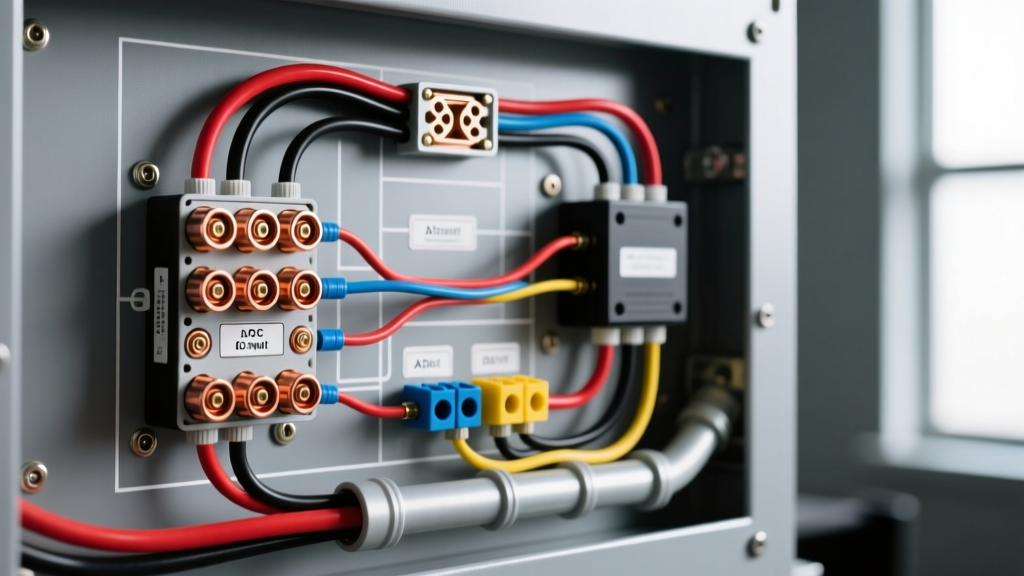
The Anatomy of a Heavy-Duty Truck Inverter Wiring Diagram
Whether you are outfitting a Ford F-150 with a 1000W pure sine wave unit or wiring a 3000W modified sine wave inverter into a Ram 2500 work truck, understanding the underlying truck power inverter wiring diagram is critical for safety and performance. Unlike low-draw accessories, high-wattage inverters pull massive DC current from the vehicle's charging system. A 2000W inverter, for example, can draw upwards of 185 amps at 12V DC under peak load.
A proper heavy-duty inverter schematic bypasses the factory fuse box entirely for the main power feed. The core diagram consists of four primary circuits: the high-current DC positive feed, the heavy-gauge DC ground return, the remote ignition sense trigger, and the 120V AC output distribution. When an inverter fails to power AC loads, or shuts down unexpectedly, the issue rarely lies within the inverter's internal logic board. Instead, 90% of failures stem from voltage drop, inadequate grounding, or failed remote solenoids. Below is a comprehensive, step-by-step troubleshooting flow designed for automotive electrical technicians and advanced DIYers.
Step-by-Step Troubleshooting Flow: Diagnosing AC Output Failures
Follow this sequential diagnostic flow to isolate the fault. Do not skip phases, as a poor ground will mimic a failed internal inverter board.
Phase 1: The DC Input and Grounding Audit
Before touching a multimeter, perform a physical audit of the high-current connections. High-amperage DC circuits are highly susceptible to thermal expansion and vibration-induced loosening.
- Verify Fuse Proximity: Per Blue Sea Systems circuit protection guidelines and ABYC/SAE standards, the main overcurrent protection device (ANL or Class T fuse) must be located within 18 inches of the battery positive terminal. If the fuse is mounted near the inverter, the entire length of the battery cable is unprotected against a short-to-ground.
- Torque Check: Inspect the DC+ and DC- terminal lugs on the inverter chassis. For 2 AWG or 1/0 AWG copper lugs, the terminal nuts must be torqued to 12-15 ft-lbs. Hand-tightened wing nuts or improperly crimped set-screw lugs will create high-resistance hotspots that trigger the inverter's thermal shutdown protection.
- The Grounding Fallacy: Never ground a >1000W inverter to the truck bed or a painted chassis bracket. Truck beds are isolated from the main frame by powder coating and rubber isolators, relying on thin braided ground straps that cannot handle 150A+ returns. The DC- cable must be terminated directly to the battery negative terminal or a dedicated, unpainted frame rail grounding stud cleaned down to bare metal.
Phase 2: Voltage Drop Testing Under Load
If the inverter powers on but shuts down when you plug in a high-draw AC tool (like a 12A miter saw), you are experiencing severe voltage sag. Inverters have a Low Voltage Disconnect (LVD) typically set around 10.0V to 10.5V to protect the truck's starting battery.
- Set your Digital Multimeter (DMM) to DC Voltage.
- Place the red probe directly on the inverter's DC+ terminal and the black probe directly on the inverter's DC- terminal (not the battery).
- Turn the inverter on and apply the AC load.
- Interpret the Reading: A healthy system should maintain at least 11.5V under load. If the DMM reads 10.4V or lower, you have excessive resistance in the cabling.
- Isolate the Drop: Move the DMM probes to the battery terminals. If the battery reads 12.2V while the inverter terminals read 10.4V, you have a 1.8V drop across your cables. This indicates undersized wire (e.g., using 4 AWG instead of 1/0 AWG) or severe corrosion inside the battery terminal clamps.
Phase 3: Ignition Sense and Relay Solenoid Diagnostics
To prevent the inverter from draining the truck's battery when parked, high-power diagrams utilize a heavy-duty continuous duty solenoid (e.g., Cole Hersee 24059) controlled by a remote ignition sense wire. If the inverter has DC power but refuses to turn on via the remote switch, troubleshoot the trigger circuit.
- Pin 86 (Coil Positive): This wire (usually 14 AWG or 16 AWG yellow/red) connects to an ignition-switched source. In Ford Super Duty trucks utilizing Upfitter Switches, Aux 1 (Orange/Yellow) or Aux 2 (Blue/White) are ideal trigger sources. Verify 12V+ here only when the key is in the 'Run' position.
- Pin 85 (Coil Ground): Must have a clean path to chassis ground. Test for continuity to the battery negative.
- Pin 30 & Pin 87 (High Current Contacts): Pin 30 receives battery voltage. Pin 87 feeds the inverter's remote 'ON' switch or directly enables the inverter's internal logic. If the solenoid clicks but the inverter doesn't wake up, use a test light on Pin 87 to verify the heavy contacts haven't burned out internally—a common failure mode when solenoids are subjected to high-current inductive spikes without a diode snubber.
Phase 4: Internal Inverter Faults and AC Output Verification
If DC input voltage is a solid 12.6V, grounding is verified, and the remote trigger is active, the fault may lie in the AC output stage or internal MOSFETs.
- Set your DMM to AC Voltage (True RMS preferred).
- Measure across the hot and neutral slots of the inverter's GFCI receptacle. You should read 115V-120V AC.
- GFCI Tripping: If the outlet reads 0V and the GFCI reset button is tripped, look for moisture ingress or a neutral-to-ground bond fault. Many truck-mounted inverters are installed in bed boxes where condensation builds up inside the AC outlet housing.
- Cooling Fan Failure: Listen for the internal PWM cooling fans. If the inverter reaches 140°F internally due to a seized fan, the thermal sensor will hard-lock the unit. Clear any debris blocking the chassis heatsink fins.
Truck Power Inverter Wire Gauge & Overcurrent Protection Chart
Selecting the correct wire gauge and fuse size is dictated by the inverter's continuous wattage and the length of the cable run. The following chart assumes a standard 12V nominal truck electrical system and cable runs under 15 feet (total round trip). Always adhere to SAE J1128 standards for low-tension primary cable insulation ratings.
| Inverter Wattage | Max DC Draw (Amps) | Minimum Wire Gauge (AWG) | Recommended Fuse Type & Size |
|---|---|---|---|
| 400W - 800W | 75A | 4 AWG | 100A MAXI / ANL |
| 1000W - 1500W | 140A | 2 AWG or 1 AWG | 150A ANL |
| 2000W | 185A | 1/0 AWG | 225A Class T |
| 3000W | 280A | 2/0 AWG or 3/0 AWG | 300A Class T |
Note: Class T fuses are mandatory for systems exceeding 1500W due to their high interrupt capacity (AIC), which safely extinguishes the arc during a catastrophic short circuit on high-amperage lithium or dual-battery truck setups.
OEM vs. Aftermarket: Truck-Specific Wiring Quirks
When integrating an aftermarket inverter into a modern truck, you must account for the vehicle's CAN bus and smart alternator systems. Trucks like the 2021+ Ford F-150 with Pro Power Onboard or GM Silverados with the Duramax 3.0L utilize high-voltage DC-DC converters tied directly to the 48V or high-output 12V bus.
If you are tapping into a smart alternator circuit, be aware that the alternator may drop system voltage to 12.2V or lower during deceleration to save fuel. This 'smart charging' profile can trick an aftermarket inverter into thinking the battery is dead, triggering a low-voltage alarm. To resolve this, wire the inverter's ignition sense circuit to a dedicated auxiliary upfitter battery (isolated via a Voltage Sensitive Relay) rather than the main cranking battery, ensuring a stable 12.8V+ reference for the inverter's logic board.